• Please visit and share your knowledge at our sister communities:
  • If you have not, please join our official Homebrewing Facebook Group!

    Homebrewing Facebook Group

Terminal Block Usage

Homebrew Talk

Help Support Homebrew Talk:

This site may earn a commission from merchant affiliate links, including eBay, Amazon, and others.

BeardedBrews

Well-Known Member
Joined
May 11, 2015
Messages
1,265
Reaction score
564
Location
Tacoma
Quick regarding the typical paired connector terminal blocks.

Is it generally required that each block house only one branch (L1, L2, G, N), or is it reasonable to use half of the block for one branch and half for the other?

Similarly, is it considered acceptable to double spade (or ring) connectors on a single screw?
 
Last edited by a moderator:
It is common to have multiple supply voltages on a single terminal strip. When you have blocks sharing multiple voltages, you will sometimes find a physical barrier at the point where a group of terminals at one potential transitions to another group at a different potential.
Some of the better terminal strips have buss bar attachments that allow putting groups of terminal in common.

Regarding multiple wires under a single terminal, best wiring practices avoid this. Piling wires under a single screw terminal is a poor wiring practice and makes it more likely that the terminal will loosen over time.
 
Last edited:
apologies if this should be in it's own thread, but what about the use of a longer bolt instead of a terminal strip, with multiple ring terminals placed on it and held down with a nut, or alternatively, multiple stacked terminals/ nuts (which would keep it from coming unscrewed) or using a lock nut at the top.
 
apologies if this should be in it's own thread, but what about the use of a longer bolt instead of a terminal strip, with multiple ring terminals placed on it and held down with a nut, or alternatively, multiple stacked terminals/ nuts (which would keep it from coming unscrewed) or using a lock nut at the top.

What you are describing is not typically done in professionally assembled panels. Would it work? Maybe? Would a UL inspector approve the panel for commercial manufacture? Not likely.
Would I want to be the guy who had to troubleshoot a problem in a panel assembled that way? Nope.
 
What you are describing is not typically done in professionally assembled panels. Would it work? Maybe? Would a UL inspector approve the panel for commercial manufacture? Not likely.
Would I want to be the guy who had to troubleshoot a problem in a panel assembled that way? Nope.
oh, i know, and i wont be doing that, just a suggestion because OP potentially has space issues that necessitate the desire to stack a few ring terminals... i don't see the theoretical difference between this idea and a solid bus bar w/ multiple bolt/screws holding multiple ring terminals down, as the surface contact area should be basically the same, but yeah, not worth the few $ difference for a larger terminal block if space is available.
 
I'm not a professional, so I can say whatever I like. When I need to bring more than two wires together, I bring the source wire into one side of a terminal strip, then run jumpers to as many terminals as I need. Then connect the other wires to the individual terminals on the other side. This is neither professional nor to any code I ever heard of, but it gives you as many terminals as you need, with no more than two wires per screw. In effect, you turn a terminal strip into a bus bar. This is wrong and no one should ever do it, but it works for me. I may even be using the wrong words. Maybe I mean barrier strip. The thing with a row of screws on each side. Did I remember to say I'm not a professional?
 
When I need to bring more than two wires together, I bring the source wire into one side of a terminal strip, then run jumpers to as many terminals as I need. Then connect the other wires to the individual terminals on the other side.

I have seen this technique used in more than a few commercially wired panels. I don't believe there is anything inherently wrong with this when the correct size of wire is used.
 
I'm not a professional, so I can say whatever I like. When I need to bring more than two wires together, I bring the source wire into one side of a terminal strip, then run jumpers to as many terminals as I need. Then connect the other wires to the individual terminals on the other side. This is neither professional nor to any code I ever heard of, but it gives you as many terminals as you need, with no more than two wires per screw. In effect, you turn a terminal strip into a bus bar. This is wrong and no one should ever do it, but it works for me. I may even be using the wrong words. Maybe I mean barrier strip. The thing with a row of screws on each side. Did I remember to say I'm not a professional?

there is nothing inherently wrong with what you describe and a very common installation technique, although many professional panels use jumper bars/combs rather than individual conductors to tie several terminals to the same potential point. it is one of the few options available for terminals that are only rated to accept one conductor yet multiple conductors need to be at the same potential.

and when i say there is nothing 'inherently' wrong, this presumes the conductors are within the size range of the terminal, everything is properly torqued down, etc. also, many terminals are in fact rated to accept more than one conductor but rarely more than two. the instruction sheet that comes with the terminals should indicate size range of conductors the terminals will accept, maximum amount of conductors per terminal, proper torque setting for a secure connection and any other installation/use requirements.
 
These lever nuts work very well as an alternative to terminal strips/crimped lugs:

61EXwd9as9L._SL1000_.jpg
 
These lever nuts work very well as an alternative to terminal strips/crimped lugs:

61EXwd9as9L._SL1000_.jpg

How do these attach to the subpanel? Also, How do these maintain pressure on the conductors? Are these spring loaded or some sort of cam-locking action?
 
They are basically a replacement for wire nuts, but allow more wires in a much more positive and reliable connection. I don't have or need them attached to the panel..they just sit inside
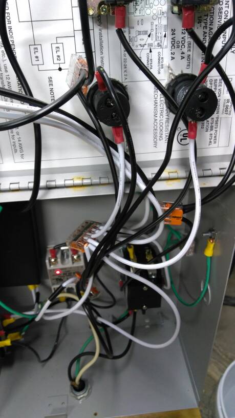
IMG_20171202_194024903.jpg
 
The Blue Seas terminal strips and jumpers are fine to use. You can also double-stack spades or rings on those screws as long as you orient the terminals "back to back." For a single stud-type connection like the ground lug inside an enclosure, the rule of thumb is no more than three terminals.

As far as those Wago wire nut replacements, that picture is an illustration of how well-meaning people get shocked. There are exposed conductors. There are wires that are unsupported and hanging loose. There are multiple conductors in a slot designed for a single conductor. Further up in the picture, there are at least four connections with exposed conductors entering what appear to be crimp terminals that are the wrong size for the wire being terminated. It also looks like the SSR in the bottom part of the picture is using the enclosure itself as a heat sink.

AC current is no joke. It can kill you, and it doesn't negotiate. Mixing AC current with hot, sticky liquids is even less funny. If you are brewing with electricity and aren't fully conversant with circuits, circuit design, best practices, and published codes and standards, you should either a) carry a fat, Cadillac-grade life insurance policy, or b) get someone who knows what the f**k they're doing to look over and correct the raw hackery that you come up with.

I dislike being blunt like this, but I've seen enough really bad safety issues in the threads on this topic that I think that someone new to the hobby is going to think that workmanship like this is OK, and wind up getting hurt or killed.
 
Last edited:
These lever nuts work very well as an alternative to terminal strips/crimped lugs:

61EXwd9as9L._SL1000_.jpg

I am not a fan of wirenuts or similar connectors in control panel wiring. As rnorman57 points out, they provide no support for the wiring on their own.

Ever had to troubleshoot a problem or measure voltages in wire nut connections? It is a real pain due to limited access to the connection with meter probes and the fact that they are usually flopping around loose.

They are fine for use in smaller junction boxes and are used extensively for electric power distribution.

Using the panel (or sub-panel) as the heat sink for an SSR is not necessarily a bad practice if you understand the maximum heat dissipation requirements of the device, and the panel has adequate surface area to dissipate that heat. The SSR doesn't care how the heat is dissipated, just so long as it is.

Those Wago devices are fine...as long as there is no exposed copper hanging out. Same with wire nuts, as long as there is no vibration in the environment. My gripe is with the multiple conductors crammed into one hole and bare copper sticking out and the total lack of support for the wiring in that box.

Concur about the heat sink, too. That's not so much an electrical safety issue as it is a "best practice" issue. Steel is nowhere near as efficient at dissipating heat as aluminum. Also, a 40A SSR on full-tilt boogie for an hour is going to create a bit of a hot spot on that enclosure. Tough break for a little kid that leans up against the enclosure. A heat sink for that SSR is $5 from Amazon.

I'm also not a huge fan of using electrical tape to re-code wire color. Might not be an explicit NEC violation, but it'd much better to use a piece of heat shrink tubing.
 
Sometimes its a fuzzy line between just-adequate wiring practices and a professionally constructed/wired panel.

One area where the two extremes become evident is wire/cable management. Look at a professionally wired panel and you have to work hard to see more than an inch or two of a single exposed wire anywhere.
Its all neatly routed in covered wire duct and the panels are near-works of art.

Professionally wired panels with an exposed, neatly bundled wire harnesses are even more impressive to me. When done right, every single conductor is perfectly parallel, laced tightly, all turns are right-angles, and you have to look hard to find a crossed conductor anywhere.
 
Professionally wired panels with an exposed, neatly bundled wire harnesses are even more impressive to me. When done right, every single conductor is perfectly parallel, laced tightly, all turns are right-angles, and you have to look hard to find a crossed conductor anywhere.


Those are actually lots harder to work on. Covered tray presents a neat appearance, and there is room to leave a service loop of extra cable in the event repairs are needed.
 
Here's a pic of a project we just completed. It's an in-process pic of one section of a switchboard cabinet we installed in a big motor yacht. Note the block of wood on the lower-right corner of the pic. It's holding Stransnap sticks used to mark every wire with a number referenced on the schematics. That's the real key to being able to troubleshoot a system quickly.

Photo 9 05 21 AM.jpg
 
That's a great looking panel.

No question, a panel wired with wire duct is much more practical. Easier to wire, easier to modify, and easier to service later on.

A exposed wire harness is a bear to trace wires through if its not labeled and documented properly. Future additions are hard to add and have look right.
All those issues go away with wire duct.
I appreciate the appearance and skill to assemble a well executed wire harness. But given the choice, I would much prefer a duct system for all the reasons mentioned.
I am dating myself, but I entered into the profession at a time wire duct was just becoming popular.
 
i'll echo @GParkins comments about the exposed conductor. when using crimp lugs, the sleeve end on the crimp should be over the wire insulation such that no bare conductor is exposed. at first glance, it would appear too much insulation was removed when making the crimp. just as too little exposed conductor is a problem, too much is also a problem. follow manufacturer's recommendations on amount of insulation to remove. similar deal with more than one conductor under each terminal, the terminals are only listed for one conductor per terminal. photo looks like two conductors were twisted together and then inserted in the terminal. the whole purpose of the terminals is to eliminate those types of connections.

regarding wire color, the nec doesn't really apply here but best practice would be not to tape wires, especially since the lengths are so short. white wires tapped black typically is used for switch legs when romex is used. the cable comes with only black and white conductors so the white is taped to indicated it is switched, while the black is always hot. the same could be taking place here in this panel but since these are individual conductors, no reason not to grab a different color wire.
 
the sleeve end on the crimp should be over the wire insulation such that no bare conductor is exposed.

Given the unsupported wiring inside the enclosure, the exposed copper is especially risky because there is no control of what those Wago blocks do when the cover is closed.

Anything routed to the lid of the enclosure should be carefully strapped to form a hinge that articulates with the door and doesn't put any stress on the conductors and/or terminals on either end of the wires as the door opens and closes.

in general, i would agree with you on the described installation technique but for this type of installation, the use of mechanical connectors 'floating' in the panel should not be of great concern, provided they are terminated properly and adequate slack is provided in the wire for opening the door, etc. those wago connectors make for very strong, secure connections, much better than twisting conductors together and using wire nuts. that being said, i'm a neat freak when it comes to wiring and a 'spaghetti bowl' of conductors inside the panel is in my opinion unsightly and difficult to troubleshoot.
 
but for this type of installation, the use of mechanical connectors 'floating' in the panel should not be of great concern, provided they are terminated properly and adequate slack is provided in the wire for opening the door, etc.

In a small enclosure with no equipment installed on the door, I agree with this. However, there are what look like AC-powered pilot lights (with exposed conductor on the black wires) mounted to the door, and that Wago block looks to be pretty close to the top of the pile inside the enclosure. I'd feel a lot better if that Wago block was secured. Although the whole door is not visible in the pic, so I can't say for sure that there isn't one, there should be a ground jumper connecting the door to the enclosure itself.
 
Back
Top