• Please visit and share your knowledge at our sister communities:
  • If you have not, please join our official Homebrewing Facebook Group!

    Homebrewing Facebook Group

Switch Wiring for 240v Contactor

Homebrew Talk

Help Support Homebrew Talk:

This site may earn a commission from merchant affiliate links, including eBay, Amazon, and others.

WhiteArmadilloBrewing

Well-Known Member
Joined
Jul 28, 2017
Messages
81
Reaction score
5
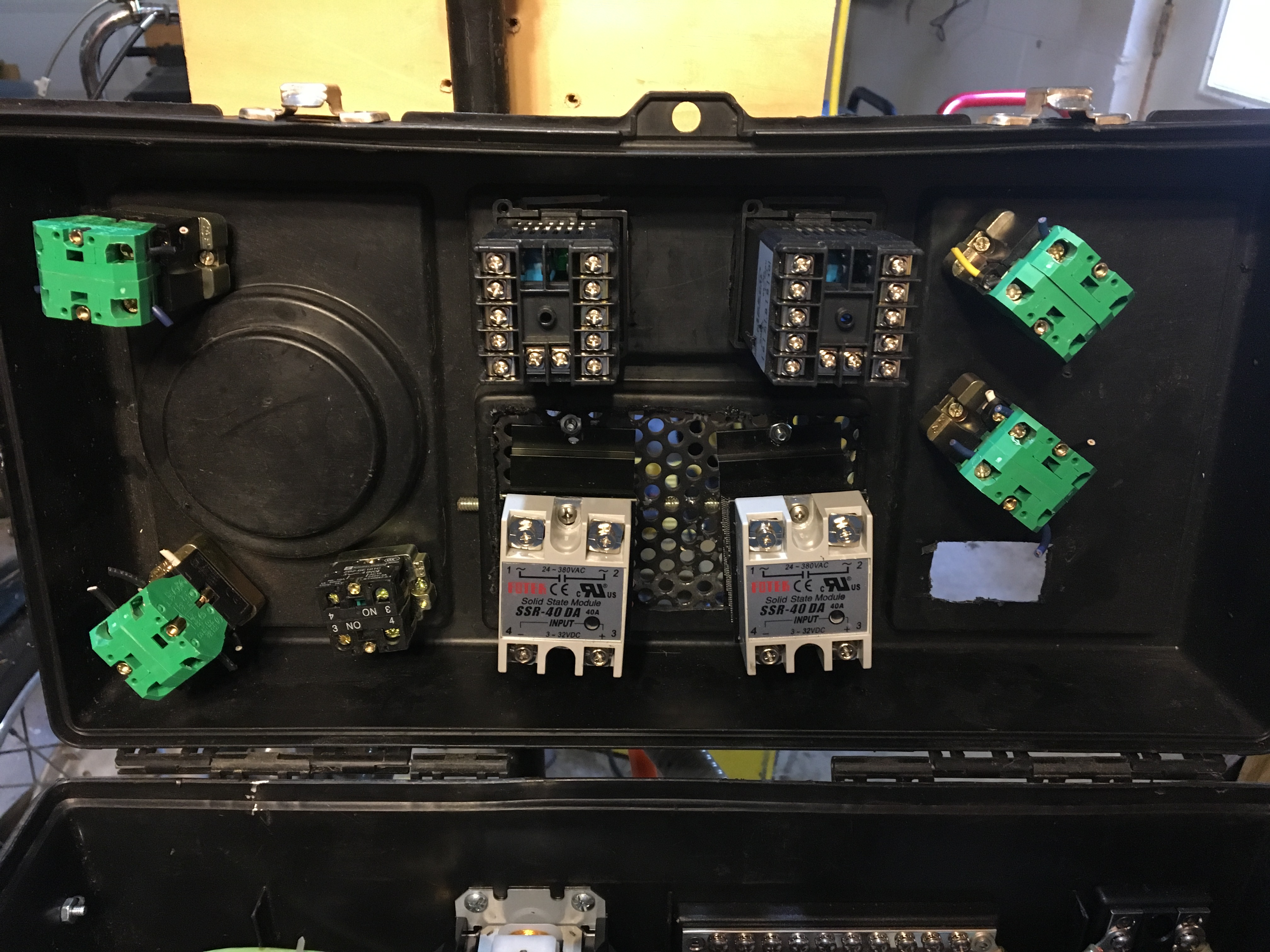
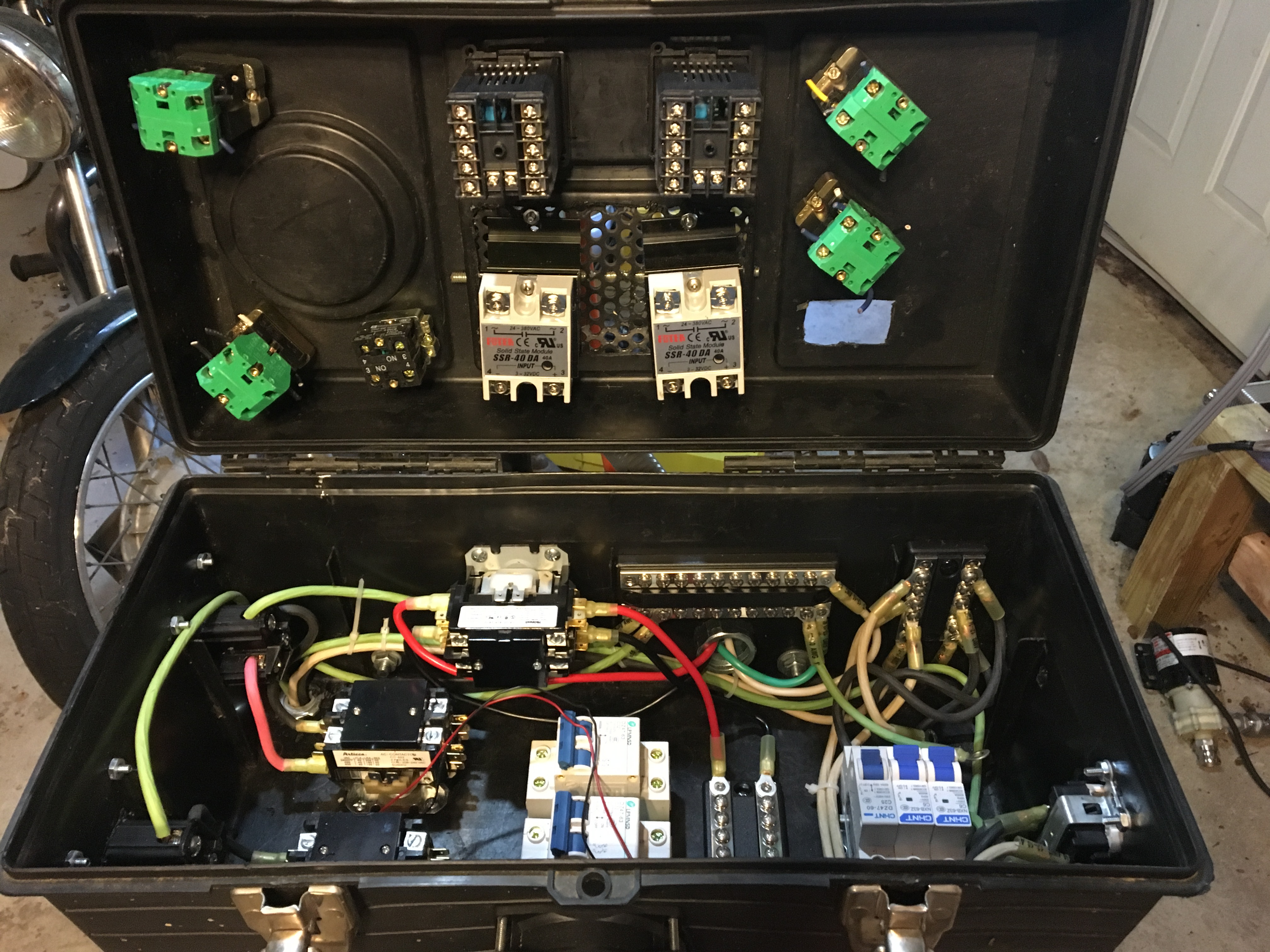
I've got a 240v 40a 2-Pole Contactor that I want to use in conjunction with a rotary selector switch as the main power switch to my control panel. I've got the two hot leads from the spa panel connected to the contactor and then to my bus bars. I'm confused on how to wire the switch though. It's a standard 22mm 10a rotary selector switch. In the past (on my coffee roaster) with a 120v power source I connected the hot and the neutral and it was pretty simple.

How do I wire up this rotary switch with two hot leads? Or, do I need a different switch to ensure both hot legs are on/off when the switch is in the proper position?
 
Who is the switch supplier and what is the PN? Normally you would control the main power contactor with a simple two position on-off switch (SPST.) A selector switch is usually used to select between two or more contactors.

Brew on :mug:
 
Your post is a little confusing. So this is a 3-position switch, or you're just referring to 4-wire 240v hot lines? If the former: Use a multimeter to test continuity and figure out which position you want to be the "on" output and wire that one to the contactor coil. The other lug is for the other "on" position. The other lead goes to neutral/common.

If the switch is rated for 120v, it can be powered from one of the hot leads. Using 1 hot means the output voltage will be 120v, but you must use neutral. Hot to the negative switch lug, switch "on" lug to contactor coil, neutral wire from bus to the other end of the contactor coil. Then when the switch is turned on, the circuit is closed, the contactor coil draws a magnetic charge, and closes the circuit it is controlling.
 
Last edited:
How do I wire up this rotary switch with two hot leads? Or, do I need a different switch to ensure both hot legs are on/off when the switch is in the proper position?

240v basically has neutral built in because of how the transformer steps down secondary, so neutral is not needed when both hot lines are used. 120v needs a neutral. See here for an explanation:
https://diy.stackexchange.com/questions/33602/why-do-240v-circuits-not-require-neutral

You really don't need both hot lines going to a bus unless you have multiple components running on 240v. Both the hots should be going into the contactor. One should go out to a bus, and the other should go into the SSR to control duty cycles (presuming you're using a PID controller to control a heating element). The neutral should go straight to a bus, as you will likely have multiple 120v components to connect. NO power is going into the circuit until power is going to the coil in the contactor. So wire up a switch from ONE hot lead to the coil. Then wire the other end of the coil to neutral. Additionally, if you wanted to use any other switch or component rated for a lower voltage, you would need a transformer to step down the voltage. In that case, you could use 1 hot line, and you would want 120v primary to whatever secondary voltage was needed.
 
Last edited:
I was looking at this diagram I found which spurred on my original question, but it also applies to the additional contactors I have connected to my element outlets. I have illuminated selector switches that I want to connect to each element contactor so (1) I can control the power to them (2) know they're on when I do.

The element contactors will be wired to an SSR + PID but the main contactor will control power to the entire panel then run to a bus so that the element contactors can draw power. After reading through your previous post, though, are you saying I can wire the additional contactors directly to the main contactor and achieve the same thing without need any bus bars?
 

Attachments

  • contactor.jpg
    contactor.jpg
    31.3 KB
You should double check the coil voltage on you contactor coils. Many contactors rated to switch 240V, or more, have 120V coils. Also you need to check the rated voltage on the LED lamp in your lighted switch. A 240V LED will run, at reduced brightness, on 120V, but 240V will blow out a 120V LED. The previous two items make a difference in how things are wired.

Brew on :mug:
 
Last edited by a moderator:
Ok, the contactor's coil is 240v so you're good to go. L1 hot can go to one coil terminal. L2 hot goes to terminal 4 on the switch and then terminal 3 on the switch goes to the other coil terminal.
 
Ok, the contactor's coil is 240v so you're good to go. L1 hot can go to one coil terminal. L2 hot goes to terminal 4 on the switch and then terminal 3 on the switch goes to the other coil terminal.

Don't I need to run 10g wire to/from the coils? If so, it looks like the gauge wire used on the switches is 18g?
 
Here are pics of the inside of my control panel build. The two coils on the left are wired to my element receptacles. All the stuff on the right is for my 120v pump & RIMS receptacles and the coil mounted on the side of the panel is the one that is currently connect to my main power source coming from the spa panel.

As you can see nothing is totally wired yet because I want to ensure its correct and safe so if you see any other issues please let me know.
 

Attachments

  • IMG_1092.JPG
    IMG_1092.JPG
    2 MB
  • IMG_1090.JPG
    IMG_1090.JPG
    2.3 MB
  • IMG_1091.JPG
    IMG_1091.JPG
    2.1 MB
Don't I need to run 10g wire to/from the coils? If so, it looks like the gauge wire used on the switches is 18g?

No, the coil activation circuit is only going to draw miliamps so you can use 18 gauge wire to the coil, to the switch and from the switch to the coil.

Of course just as you mentioned the high current lines run to and from the switched side of the contactor and on to the element. The reason was use a contactor in the first place is so that the manually operated switches carry low current.
 
Those switches are only rated for 120V AC, and the lamp is also only rated for 120V. To use them, you should switch both hots going to the contactor coil (one ho thru each switch block), and then X1 gets connected to neutral, and X2 gets connected to the load side of one of the switch blocks. X1 & X2 are the lamp connections.

Brew on :mug:
 
...

As you can see nothing is totally wired yet because I want to ensure its correct and safe so if you see any other issues please let me know.
With the way your heatsinks are mounted inside the control box, you will get very little air flow over the heat sinks. There is a high probability you will have SSR overheating issues with this mounting scheme. There is a reason most designs have the heatsinks outside the enclosure, or have internal fans blowing air across the heatsinks (plus entrance and exit air vents.)

Brew on :mug:

Yea, I've read that all over these forums. You can't see it in the picture but I have a CPU fan mounted on the front of the enclosure and blow air across the SSRs out of the panel (they're mounted to perforated steel).
 
Those switches are only rated for 120V AC, and the lamp is also only rated for 120V. To use them, you should switch both hots going to the contactor coil (one ho thru each switch block), and then X1 gets connected to neutral, and X2 gets connected to the load side of one of the switch blocks. X1 & X2 are the lamp connections.

Brew on :mug:

Just to clarify, each of the blocks on a single switch or wire each hot to a separate switch?
 
Hot 1 and hot 2 go thru different blocks on the same switch.

Brew on :mug:
Since this is just a switch to cut the power to the contactor coil, Why cant he just use the switch to switch one hot leg and turn the contctor on and off that way the way many use an ssr? Isnt it still only 120v on that line regardless of whether its combined with another 120v line to create 240v down the line? Does it all have to be rated for 240v to be used this way for code?
 
For an element control contactor, just switching one of the hot lines will work. In the case of the main power contactor, the idea is to physically disconnect as much of the power inside the enclosure as possible, so both hots should be switched.

If you wire one hot leg of a 240V loop thru a switch, and the loop contains a contactor coil, when the switch is open, you will measure 240V between the switch terminals. That being said, I'm not sure just what the 120V contact rating means. The switch's insulation is rated to 600V (IIRC.) The contact ratings are 6.5A @ 120VAC, but for a coil you only switch milliamps, so I don't see where it would be a real problem.

Brew on :mug:
 
Back
Top