• Please visit and share your knowledge at our sister communities:
  • If you have not, please join our official Homebrewing Facebook Group!

    Homebrewing Facebook Group

Stc-1000+

Homebrew Talk

Help Support Homebrew Talk:

This site may earn a commission from merchant affiliate links, including eBay, Amazon, and others.
Thanks for all your hard work on the STC, Alphaomega, I have my mini all programmed up and waiting for my STCs to arrive so I can program them. I want to leave the header pins and the mini connected so I can upload profiles as and when needed.
One thing I would like to try and wonder if anyone else has tried is having a battery backup/clock so if there is a power cut the STC knows where it is up to (or are you gona tell me it already does that;)).
Either a board that can piggyback to the stc on the right pins, maybe a 9v battery that monitors the 5v line and if it drops below kicks in?
We get the odd short power dropout occasionally in winter so could be a bummer if you have to reprogram from a few days in etc or don't know it's gone out.

Anyway I just had to say thanks for a fantastic project.
 
Your easiest solution for that might be to get an UPS like you would for a computer. As long as your power issues don't last for long the ups should be able to run the stc-1000 and the fridge for some time. That would probably make for the quickest and easiest solution (but maybe not the cheapest).
 
One thing I would like to try and wonder if anyone else has tried is having a battery backup/clock so if there is a power cut the STC knows where it is up to (or are you gona tell me it already does that

It already does that. :ban:

Every hour, current duration, dh (and if next step is reached, also current step, St) is updated with new value(s). That means in case of a power outage, STC-1000+ will pick up (to within the hour) from where it left off.
https://github.com/matsstaff/stc1000p/blob/master/usermanual/README.md
 
Thanks for all your hard work on the STC, Alphaomega, I have my mini all programmed up and waiting for my STCs to arrive so I can program them. I want to leave the header pins and the mini connected so I can upload profiles as and when needed.
One thing I would like to try and wonder if anyone else has tried is having a battery backup/clock so if there is a power cut the STC knows where it is up to (or are you gona tell me it already does that;)).
Either a board that can piggyback to the stc on the right pins, maybe a 9v battery that monitors the 5v line and if it drops below kicks in?
We get the odd short power dropout occasionally in winter so could be a bummer if you have to reprogram from a few days in etc or don't know it's gone out.

Anyway I just had to say thanks for a fantastic project.
I was told that leaving the pro mini and stc connected is a bad idea.something to do with with the power.
 
Ok BigDaddy, I see now why everyone just leaves the header leads accessible and not the board attached.....thanks.
And sounds like the odd power outage won't be a problem.
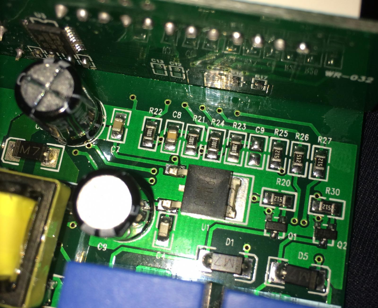
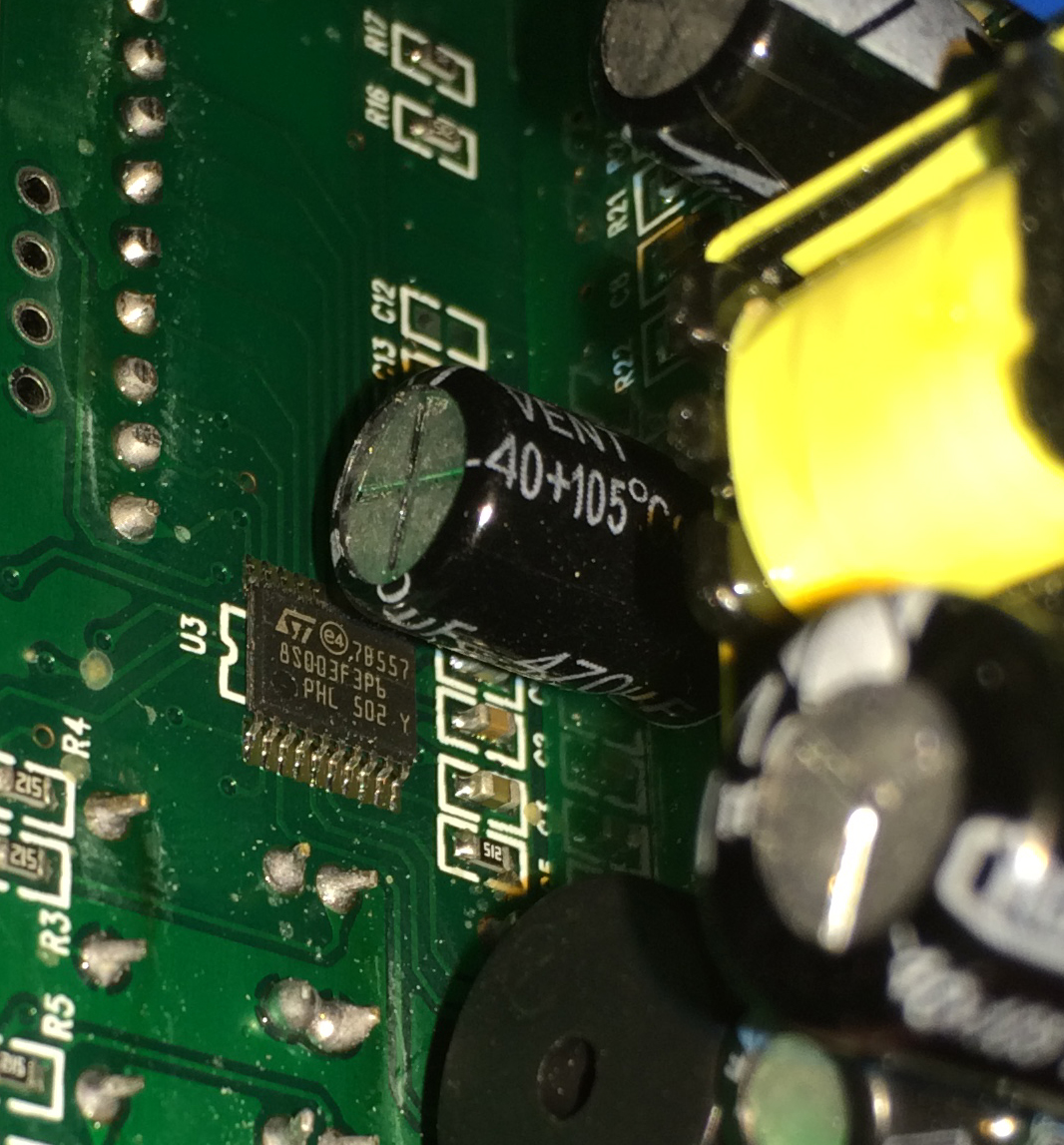
I have a couple of STCs ordered from the supplier Alpha recommended, however I have a couple of units here that have 8S003f3P6 chips and the headers are on the board. Do you think if I try and track the correct pins, this would accept the code if I put header pins on it?
I know it's not worth changing software for but is the chip compatible?
Here is photos of the boards.

8s003f3p6.jpg


Header.jpg
 
I can have a controller to you this week if in a hurry I have them in stock in Michigan
Thanks for the offer, I think I may have contacted you recently(Via a website selling flashed units, unless I am mistaken?), I am in New Zealand and we have 230v so I don't think it was an option.
Interestingly the unit in the photo above is an STC1000 that is 110-240v, so hopefully they make the flashable unit in the 230/40 volt flavor.
Nice looking unit you have, by the way. I hope to 3d print my housing for it.

oh yeah sorry about that you are correct, I only have 110 units.
 
I got my STC 1000s yesterday x2 Yah uploaded and programmed no problems, I made the Audrino mini programmer. Wow with all the documentation and this blog so easy, you guys (particularly Alpha) have done a sterling job.
I tried soldering the headers on but with so much crap on the board I soldered onto the LED header as per the data logger instructions.
Interesting fact #1 I got the 2 units here: http://www.aliexpress.com/snapshot/6724485834.html?orderId=67727934720360 (not a surprise, as directed by Alpha)
Fun fact #2 One unit has a 3 terminal block for the probe. It is still the "K" type sensor and works fine but I suspect the middle and right terminal are for a second probe looking at your earlier direction on how to fit the second probe.
Fun fact # 3 The vendor asked me what units I wanted 110 or 220v and I said 220/40 and the units are in fact 110-230VAV 50Hz/60Hz so guess they must have switching power supply. No extra charge.
Fun fact # 4 Come on they are only so exciting. No more fun till I drinks me beer.
Next thing I want to do is 3d design then print a housing for it, at the moment one is in a sistema box fermenting my coconut stout - bit of a boring profile for for such a ingenious unit!
 
Glad you had smooth sailing!
I really don't hope they start shipping with switching power supplies. Given that these units run unsupervised for long periods of time, the transformer really seems like a safety feature of the stc. But I may be wrong, it just seems like a lot of chinese switching power supplies have had issues.
 
I ordered an Inkbird controller thats in F, and then I stumbled upon doing this flashing. Well it turns out that the board from Inkbird isnt compatible.. or at least the one I got.

I have 2 more and one of them was compatible so at least I will have one controller that can ramp and be programmed.
 
I ordered an Inkbird controller thats in F, and then I stumbled upon doing this flashing. Well it turns out that the board from Inkbird isnt compatible.. or at least the one I got.

I have 2 more and one of them was compatible so at least I will have one controller that can ramp and be programmed.

correct none of the inkbird units are compatible with alpha's software / flashing
 
Quick question - just got my STC-1000 and it says A400_P V1.1 on the board. I've read that A400_P should be fine flash (not S1000) but V1.0 is the one you want not V1.1. I haven't seen any reference to a A400_P V1.1.

The hardware matches the V1.0 based on the info in this thread and it has the programming pins where expected. I'm good to flash this bad boy?
 
Maybe it's come up here, but I don't recall seeing it.

I'm finally bringing all my parts together for full service heating and cooling of my carboys using the STC1000+. I'll be doing a post on the whole package in in a few days, but need to understand the STC1000+ in this situation.

Due to time constraints I started with an STC in thermostat mode for a lager primary, while I upgraded another chamber to support the new carboy wraps I made. They have a glycol tube for cooling and THG Heat Tape for heating. Last night I moved the carboy to the this chamber and hooked up another STC1000+ with my lager profiles. Since the primary is done, I set 1 profile to start with the Drest heating. I triple checked the sensor against a digital thermometer, a lab thermometer and the tape on the carboy. All were within about .5F so I was quite pleased.

When I initially set the profile to run, ramping from 53 to 65 over 2 days, it was a bit above 53 so it went to cooling mode initially. When I checked an hour later it had cooled back down and was neither heating or cooling. I checked again a little while later and the heating was active. This morning it was up about 2.5F, and the cooling LED was blinking, but the relay was not active. I watched for a while and it would blink a few times, then stop for a bit then start again. I then wondered, what impact does the cooling delay have on ramping where the cooling cycle is only on for a short duration? I set the delay to 1 min, and no change. It looks like it calls for cooling, but not long enough for the delay.

Has anyone encountered this 'no-op' cycling on the cooling cycle?

It just occurred to me that the cooling delay might be able to be set to zero, and I now see that it can. Does this truly mean the relay will follow the blink, absolutely? I wonder if the 1 min delay (current setting) might be better to avoid unnecessary cooling cycles when trying to ramp up. If ambient will cause the temp to increase too fast then maybe not. Maybe I'm just thinking out loud here....
 
Couple questions, what do you have your hy set to and what was it reading for temp vs the current sp? I don't think I've seen repeated blinking then not operating, then blinking again as you have stated. I think once the hy has been exceeded, it is supposed to cool/heat until it reaches the current sp, even if it skips back within range before the delay timer runs out. I guess if it is keeping your temps pretty close, I wouldn't worry too much. I have my hy set to .3, don't recall what the delay is set to, maybe a few minutes? I am using a glycol jacket and heat wrap. I haven't set the delay down lower even though I could with my setup because I am trying to cancel out any ping pong effect, but I'm not sure it makes much difference in my situation.
 
Couple questions, what do you have your hy set to and what was it reading for temp vs the current sp? I don't think I've seen repeated blinking then not operating, then blinking again as you have stated. I think once the hy has been exceeded, it is supposed to cool/heat until it reaches the current sp, even if it skips back within range before the delay timer runs out. I guess if it is keeping your temps pretty close, I wouldn't worry too much. I have my hy set to .3, don't recall what the delay is set to, maybe a few minutes? I am using a glycol jacket and heat wrap. I haven't set the delay down lower even though I could with my setup because I am trying to cancel out any ping pong effect, but I'm not sure it makes much difference in my situation.

The defaults from the profile builder page Mats created, all 0 and cd 1, hd 2, Rp 1, rn 1. I'll be home in a bit to see where it's at. The initial 2.5F rise in 8 hrs was within the ramp time, so I'll see. The hy settings must be non zero though, but I don't see any default for the unit in the manual, but I did find this:
example....temperature is greater than setpoint + hysteresis AND the time passed since last cooling cycle is greater than cooling delay, then cooling relay will be engaged.
I'll have to watch it closely tonight. Since I have a pump for cooling and heat tape for heating I'm going to set both delays to 0. And look at hy....
 
I just checked mine, I have 2 and 2 for delays, but that difference doesn't matter. Depending on what hy is set to, it may be what is causing the irregularities. Since you are also just running pumps and heat tape, maybe try hy at .3 or slightly higher. On my setup if I run it at .2 it is always trying to do something because of over/under shoot.
 
Back
Top