Stc-1000+

Homebrew Talk - Beer, Wine, Mead, & Cider Brewing Discussion Forum

Help Support Homebrew Talk - Beer, Wine, Mead, & Cider Brewing Discussion Forum:

This site may earn a commission from merchant affiliate links, including eBay, Amazon, and others.
Thanks for the offer, I think I may have contacted you recently(Via a website selling flashed units, unless I am mistaken?), I am in New Zealand and we have 230v so I don't think it was an option.
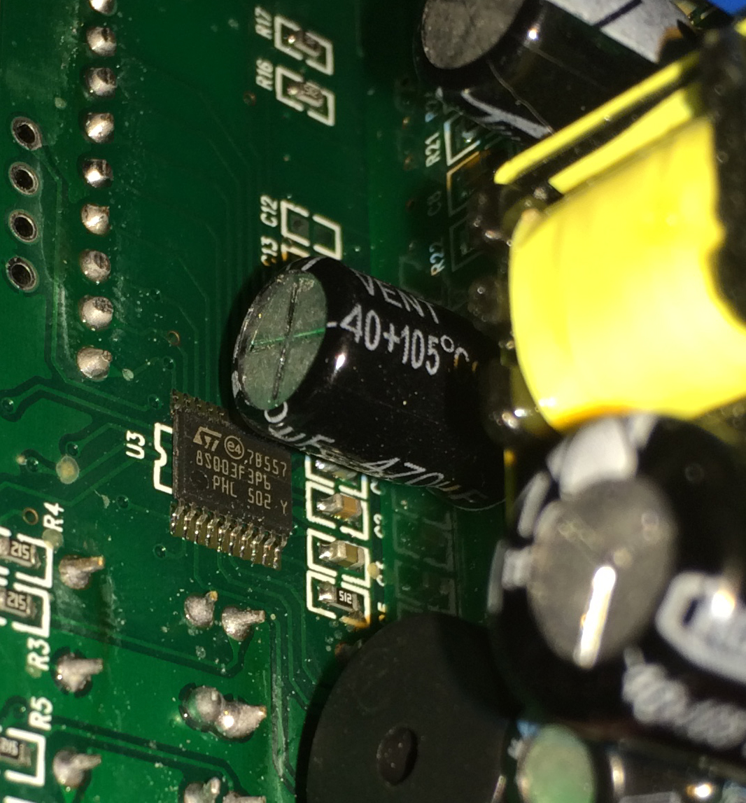
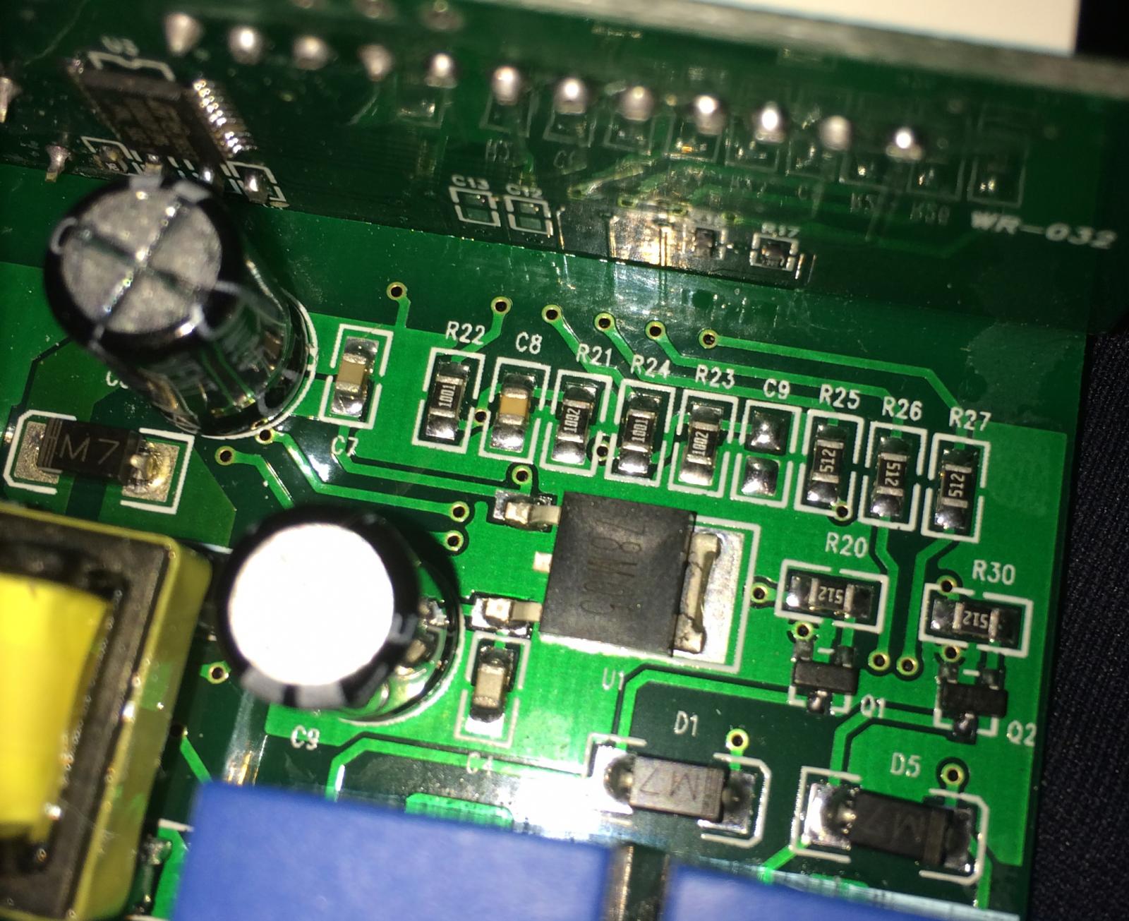
Interestingly the unit in the photo above is an STC1000 that is 110-240v, so hopefully they make the flashable unit in the 230/40 volt flavor.
Nice looking unit you have, by the way. I hope to 3d print my housing for it.

oh yeah sorry about that you are correct, I only have 110 units.
 
I got my STC 1000s yesterday x2 Yah uploaded and programmed no problems, I made the Audrino mini programmer. Wow with all the documentation and this blog so easy, you guys (particularly Alpha) have done a sterling job.
I tried soldering the headers on but with so much crap on the board I soldered onto the LED header as per the data logger instructions.
Interesting fact #1 I got the 2 units here: http://www.aliexpress.com/snapshot/6724485834.html?orderId=67727934720360 (not a surprise, as directed by Alpha)
Fun fact #2 One unit has a 3 terminal block for the probe. It is still the "K" type sensor and works fine but I suspect the middle and right terminal are for a second probe looking at your earlier direction on how to fit the second probe.
Fun fact # 3 The vendor asked me what units I wanted 110 or 220v and I said 220/40 and the units are in fact 110-230VAV 50Hz/60Hz so guess they must have switching power supply. No extra charge.
Fun fact # 4 Come on they are only so exciting. No more fun till I drinks me beer.
Next thing I want to do is 3d design then print a housing for it, at the moment one is in a sistema box fermenting my coconut stout - bit of a boring profile for for such a ingenious unit!
 
Glad you had smooth sailing!
I really don't hope they start shipping with switching power supplies. Given that these units run unsupervised for long periods of time, the transformer really seems like a safety feature of the stc. But I may be wrong, it just seems like a lot of chinese switching power supplies have had issues.
 
I ordered an Inkbird controller thats in F, and then I stumbled upon doing this flashing. Well it turns out that the board from Inkbird isnt compatible.. or at least the one I got.

I have 2 more and one of them was compatible so at least I will have one controller that can ramp and be programmed.
 
I ordered an Inkbird controller thats in F, and then I stumbled upon doing this flashing. Well it turns out that the board from Inkbird isnt compatible.. or at least the one I got.

I have 2 more and one of them was compatible so at least I will have one controller that can ramp and be programmed.

correct none of the inkbird units are compatible with alpha's software / flashing
 
Quick question - just got my STC-1000 and it says A400_P V1.1 on the board. I've read that A400_P should be fine flash (not S1000) but V1.0 is the one you want not V1.1. I haven't seen any reference to a A400_P V1.1.

The hardware matches the V1.0 based on the info in this thread and it has the programming pins where expected. I'm good to flash this bad boy?
 
Maybe it's come up here, but I don't recall seeing it.

I'm finally bringing all my parts together for full service heating and cooling of my carboys using the STC1000+. I'll be doing a post on the whole package in in a few days, but need to understand the STC1000+ in this situation.

Due to time constraints I started with an STC in thermostat mode for a lager primary, while I upgraded another chamber to support the new carboy wraps I made. They have a glycol tube for cooling and THG Heat Tape for heating. Last night I moved the carboy to the this chamber and hooked up another STC1000+ with my lager profiles. Since the primary is done, I set 1 profile to start with the Drest heating. I triple checked the sensor against a digital thermometer, a lab thermometer and the tape on the carboy. All were within about .5F so I was quite pleased.

When I initially set the profile to run, ramping from 53 to 65 over 2 days, it was a bit above 53 so it went to cooling mode initially. When I checked an hour later it had cooled back down and was neither heating or cooling. I checked again a little while later and the heating was active. This morning it was up about 2.5F, and the cooling LED was blinking, but the relay was not active. I watched for a while and it would blink a few times, then stop for a bit then start again. I then wondered, what impact does the cooling delay have on ramping where the cooling cycle is only on for a short duration? I set the delay to 1 min, and no change. It looks like it calls for cooling, but not long enough for the delay.

Has anyone encountered this 'no-op' cycling on the cooling cycle?

It just occurred to me that the cooling delay might be able to be set to zero, and I now see that it can. Does this truly mean the relay will follow the blink, absolutely? I wonder if the 1 min delay (current setting) might be better to avoid unnecessary cooling cycles when trying to ramp up. If ambient will cause the temp to increase too fast then maybe not. Maybe I'm just thinking out loud here....
 
Couple questions, what do you have your hy set to and what was it reading for temp vs the current sp? I don't think I've seen repeated blinking then not operating, then blinking again as you have stated. I think once the hy has been exceeded, it is supposed to cool/heat until it reaches the current sp, even if it skips back within range before the delay timer runs out. I guess if it is keeping your temps pretty close, I wouldn't worry too much. I have my hy set to .3, don't recall what the delay is set to, maybe a few minutes? I am using a glycol jacket and heat wrap. I haven't set the delay down lower even though I could with my setup because I am trying to cancel out any ping pong effect, but I'm not sure it makes much difference in my situation.
 
Couple questions, what do you have your hy set to and what was it reading for temp vs the current sp? I don't think I've seen repeated blinking then not operating, then blinking again as you have stated. I think once the hy has been exceeded, it is supposed to cool/heat until it reaches the current sp, even if it skips back within range before the delay timer runs out. I guess if it is keeping your temps pretty close, I wouldn't worry too much. I have my hy set to .3, don't recall what the delay is set to, maybe a few minutes? I am using a glycol jacket and heat wrap. I haven't set the delay down lower even though I could with my setup because I am trying to cancel out any ping pong effect, but I'm not sure it makes much difference in my situation.

The defaults from the profile builder page Mats created, all 0 and cd 1, hd 2, Rp 1, rn 1. I'll be home in a bit to see where it's at. The initial 2.5F rise in 8 hrs was within the ramp time, so I'll see. The hy settings must be non zero though, but I don't see any default for the unit in the manual, but I did find this:
example....temperature is greater than setpoint + hysteresis AND the time passed since last cooling cycle is greater than cooling delay, then cooling relay will be engaged.
I'll have to watch it closely tonight. Since I have a pump for cooling and heat tape for heating I'm going to set both delays to 0. And look at hy....
 
I just checked mine, I have 2 and 2 for delays, but that difference doesn't matter. Depending on what hy is set to, it may be what is causing the irregularities. Since you are also just running pumps and heat tape, maybe try hy at .3 or slightly higher. On my setup if I run it at .2 it is always trying to do something because of over/under shoot.
 
Initial indication tonight was no heat or cool. I changed the hy to 0.3, delays to 0, and it went into non-stop cooling mode. Since I want the temp to rise, not drop (only up 4.5F so far, but close to target of 12 in 48 hrs), I unplugged the pump. An hour later it's up almost another degree, and still in cooling mode, so I plugged the pump back in to see if it will stabilize. I suspect the ambient of almost 70F is causing it to rise faster than the ramp.

I looked at the current settings, using up and down arrows, and the current setpoint is 53F (same as start of ramp), and on PR1 step 0 for 1 hour. Hmm, 22 hrs in and on hour 1 still? Maybe changing the delays and hy restarted the profile?

Mats, will the up arrow current setpoint indication change (hourly?) as the ramp is running, or is it simply the starting point?

Edit - posted too soon. Now on hour 2, current setpoint is 53.8, so it's clearly changing, and the profile was obviously reset. So my Drest is delayed 1 day.

I had wanted to do a several day profile test run with water, but ran out of time with the lager as it's got to be done for a public event. Maybe it's not too late to get that test going anyway.... I have 5 STCs and 4 fermentation chambers, and the chiller is running anyway.
 
Mats, will the up arrow current setpoint indication change (hourly?) as the ramp is running, or is it simply the starting point?

It will show the current setpoint (and thusly be updated hourly when running a profile).
 
Since it got reset you can always just punch in the current temp as your starting temp and estimate how many hours are left. It should work that way, I think I had to do something similar once when I was first using these and I accidentally restarted the profile.
 
Since it got reset you can always just punch in the current temp as your starting temp and estimate how many hours are left. It should work that way, I think I had to do something similar once when I was first using these and I accidentally restarted the profile.

Depends on what you mean here. Changing SP won't work, because it will be overwritten an the next one hour mark.
The better way would be to set St and dh (the counters for the currently running profiles step and the step duration), to 'jump' to the desired place in the profile. Possibly after that set SP to a sane value so it will try to maintain a sane value for the remainder of this hour.

This makes sense. Is there a known trigger event(s) that restarts a running profile?

Had to run home at lunch, and it's .1 off the ramp point, and H&C are off. Same this morning. Looking good!
 
This makes sense. Is there a known trigger event(s) that restarts a running profile?

The way to restart a profile, would be to start the profile again (Set-rn-Prx). Changing other settings won't (or at least shouldn't), as mentioned you can jump in a running profile with St and dh, but that isn't exactly the same as restarting.
 
Oops, yeah thats what I meant alphaomega. Thanks for correcting me! I think for simplicity (since I've never jumped into a profile), setting the st to current temp and estimating how much time you want left for the dh to finish out your ramp would be easiest, at least it was for me anyway!
 
Oops, yeah thats what I meant alphaomega. Thanks for correcting me! I think for simplicity (since I've never jumped into a profile), setting the st to current temp and estimating how much time you want left for the dh to finish out your ramp would be easiest, at least it was for me anyway!

St is the current step, so I guess you mean SP :)
 
The way to restart a profile, would be to start the profile again (Set-rn-Prx). Changing other settings won't (or at least shouldn't), as mentioned you can jump in a running profile with St and dh, but that isn't exactly the same as restarting.

As I was going through all the setting last night, I could have gone to a setting and 'entered' the same value vs 'returning'.
If I 'changed' the running profile or the ramp enable by going to it's value and then hitting S, have I effectively changed that value even though it was not actually changed, thereby starting new? I suspect this may be the case if so.
 
My understanding is that the Arduino Uno should not be connected to the STC-1000 while the 120V AC power supply is connected to the unit. My question is which wires are problematic, i.e. must be disconnected. Must only the 5V and ground from the arduino be disconnected or must all of the arduino wires be disconnected from the STC-1000 board? In my build, I wanted to have the Arduino Uno mounted inside my box and permanently connected to the STC-1000 board. This way, in order to program the unit, all I need to do is attach a USB cable to my box. In order to avoid frying my build, I thought I might have (a) two two position DPDT switches with, (b) on one end, the 5V wire from the arduino and (c) on the other end, the 120V power supply to the STC-1000, and, (d) on the other switch I would have (e) the 120V neutral, and (f) the ground wire from the arduino. This would mean that, in order to supply power to the unit, I would have to disconnect the arduino, and, conversely, in order to connect the arduino, I would necessarily interrupt the 120V power supply, thus making it impossible to fry the unit. If, however, more than these two wires need to be disconnected from the arduino while the STC-1000 is powered with the 120V supply, then I would also need to add in some sort of a DIP switch or other mechanism to interrupt the remaining wires. Any input on this build plan would be greatly appreciated.
 
My understanding is that the Arduino Uno should not be connected to the STC-1000 while the 120V AC power supply is connected to the unit. My question is which wires are problematic, i.e. must be disconnected. Must only the 5V and ground from the arduino be disconnected or must all of the arduino wires be disconnected from the STC-1000 board? In my build, I wanted to have the Arduino Uno mounted inside my box and permanently connected to the STC-1000 board. This way, in order to program the unit, all I need to do is attach a USB cable to my box. In order to avoid frying my build, I thought I might have (a) two two position DPDT switches with, (b) on one end, the 5V wire from the arduino and (c) on the other end, the 120V power supply to the STC-1000, and, (d) on the other switch I would have (e) the 120V neutral, and (f) the ground wire from the arduino. This would mean that, in order to supply power to the unit, I would have to disconnect the arduino, and, conversely, in order to connect the arduino, I would necessarily interrupt the 120V power supply, thus making it impossible to fry the unit. If, however, more than these two wires need to be disconnected from the arduino while the STC-1000 is powered with the 120V supply, then I would also need to add in some sort of a DIP switch or other mechanism to interrupt the remaining wires. Any input on this build plan would be greatly appreciated.

ive actually connected both at the same time quite a number of times. No smoke yet :) I did it as a test as I knew someone would mistakenly do it on one of my pro controllers.
 
No problem keeping the arduino connected BUT you should only provide power from the USB or mains, not both at the same time. If you only intend to use the arduino to be able to reflash on occasion, then i suggest you place a diode between the arduino +5v and Vcc on the STC, so you don't 'back power' the arduino from the STC when running from mains.
 
No problem keeping the arduino connected BUT you should only provide power from the USB or mains, not both at the same time. If you only intend to use the arduino to be able to reflash on occasion, then i suggest you place a diode between the arduino +5v and Vcc on the STC, so you don't 'back power' the arduino from the STC when running from mains.

Great, thank you all very much for your help - this is great news. It sounds like building it in the way I am suggesting is unnecessary, but is a way to make it foolproof such that not even a particularly determined fool can ruin my build without opening it and rewiring it first.
 
I've not seen these 2102 boards myself, so I can't answer definitively.
I would think you don't need to remove any pin, but if you do, CTS would be my bet. @TrippleHopped had the same question, but I don't think I heard back from him how it turned out.
Please post any findings :)
Cheers!

Edit: woo hoo! Post #2000!!!
 
Back
Top