WGT_59
Member
This is actually my first thread on here :rockin:
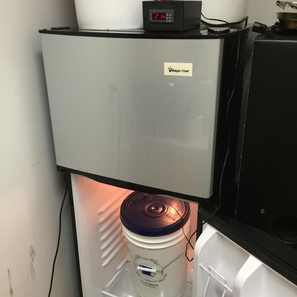
I have seen numerous plans on the internet for these and have adapted this one from several of them. Since I’m using a refrigerator that won’t always be full of fermenting wort I’ve added a bypass switch to allow the fridge to work normally. As a heat source I'll be using an old heating pad.
Suppliers:
EBay:
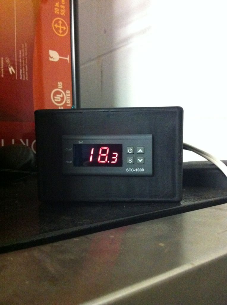
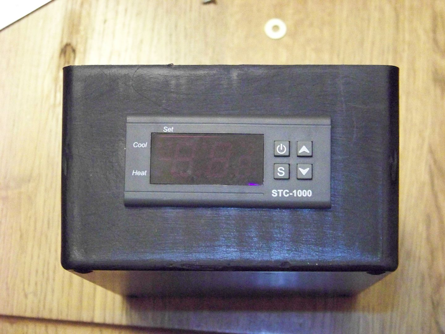
STC-1000 Available from numerous sources (12 VDC, 110 VAC, 220 VAC) ranging from $15.00 to $25.00 US.
Radio Shack:
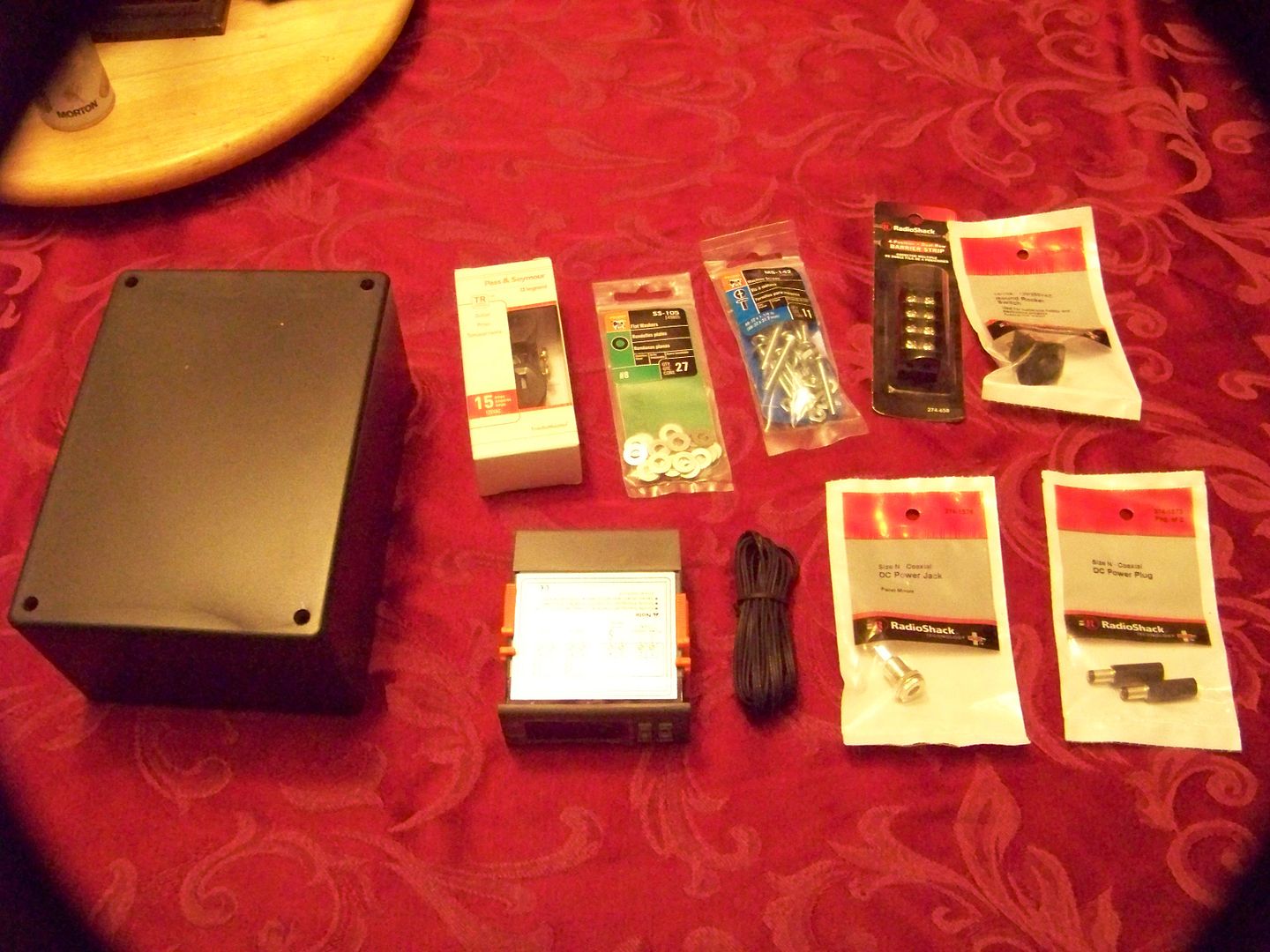
Project Enclosure $6.49 US
4 Position Terminal Block $2.49 US
Size N D/C input Plug and socket $10.00 US
10A / 125 AC SPDT Switch $8.00 US
Hook up wire, min 22 gauge, in 3 colors (lead, neutral and ground) $8.49 US
Lowes:
20 Amp Duplex Outlet with removable bridge $5.97 US
My total cost was $52.94. I picked up my STC-1000 for 19.99 with free shipping and I have a ton of PC Power Chords around and stripped my wires out of one.
Wiring Diagram.
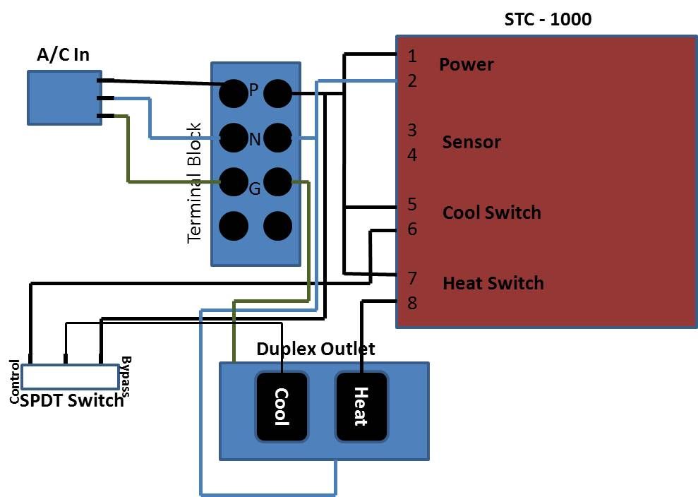
This first diagram includes the bypass switch.
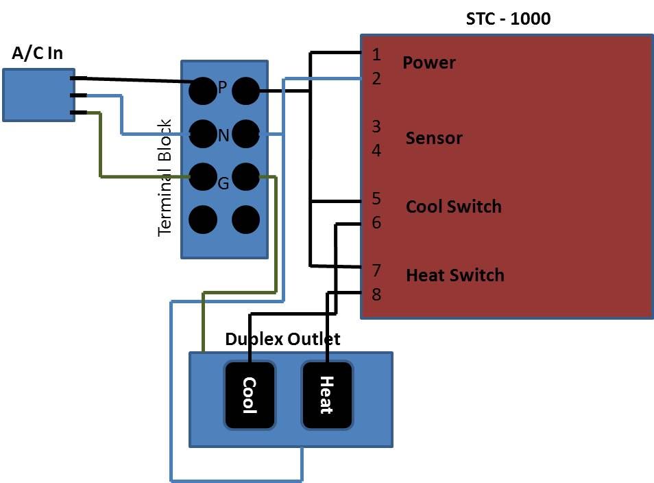
And without the bypass switch it would look like this
The controller used in this is the STC-1000 which is designed for use with Aquariums. Also it only reads in degrees C. The colors used for wires in the diagram are:
Black for the Load (P) black in the build
Blue for the Neutral (N) white in the build
Brown for Ground (G) green in the build
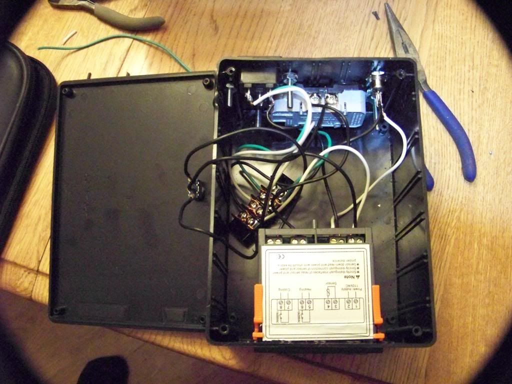
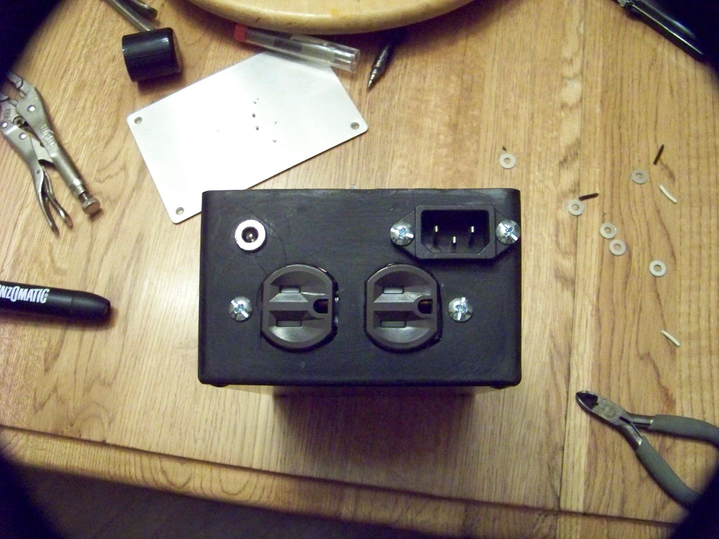
The A/C in is a 3 prong plug in like you would find on any computer. The wires off of this go into a Terminal Block.
From the Terminal Block the wires go out to:
Positive (P) 4 wires out
Connector 1, the STC-1000 power positive connector
Connector 5, the Cool In
Connector 7, the Heat In
Connection on the Bypass side of the SPDT switch.
Neutral (N) 2 wires out:
Connector 2, Power negative connector
Negative (silver) connector on the outlet
Ground (G) connects to the outlet ground connection
This leaves connections 3, 4, 6 and 8 on the STC-1000 unconnected.
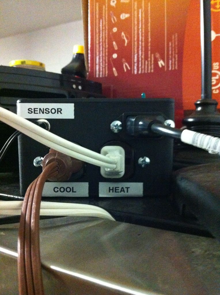
Connections 3 and 4 are for the Temperature sensor.
Connection 6 will go to control side of the switch if you’re using the Bypass or the Positive side of the Cool plug if not.
Connection 8 will go to the positive side of the Heat plug.
If using the Bypass Switch, the center position connector from the switch is then wired to the Positive side of the cool plug on the outlet.
Parts that don’t have screw mounts, such as the Terminal block, can be hot glued to the box.
Steps:
1. Mark the positions for the cuts to be made into the case for parts mounting.
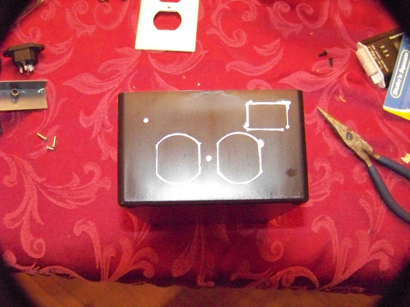
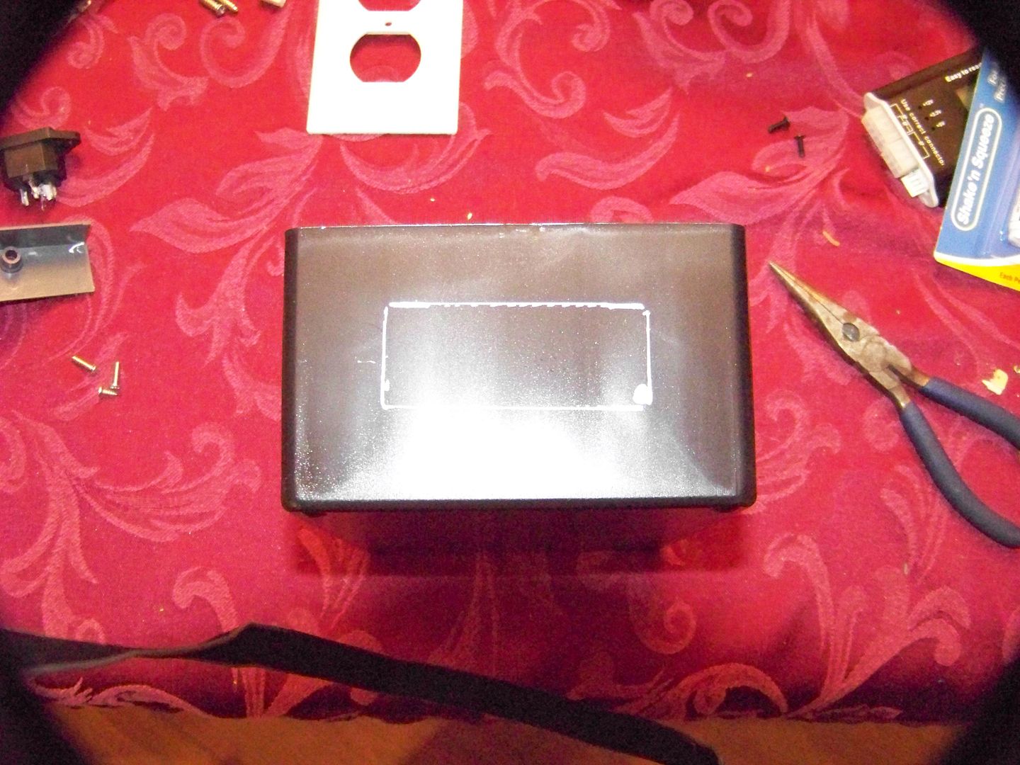
2. Cut and shape the holes. I used a Dremel and it was really simple. If you had to use a Craft Knife it could be done but would be tough going and time consuming.
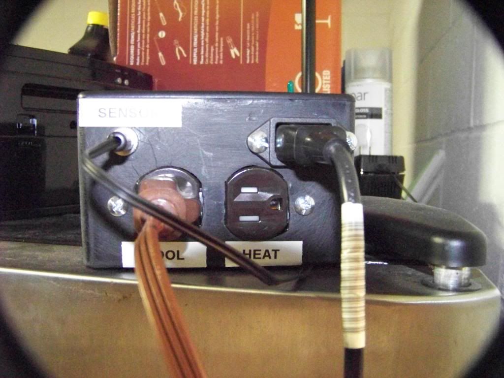
3.Remove the bridge from the Hot (Brass) side of the Duplex Plug and mount it, the Sensor Plug socket and the STC – 1000 and drill the holes for the screws where needed.
4. Solder wires to the 3 posts on the A/C input, sensor plug and socket and bypass switch if you’re using one.
5. Attach wires from Sensor Plug socket to the STC – 1000 (3 and 4).
6. Run wires from A/C input to the Terminal Block.
7. Run wires from the Terminal Block (P) to the STC – 1000 (1, 5, 7), Bypass Switch (Bypass) and the Duplex Plug (N, G).
8. Run the wires from the Bypass Switch (Control) to the STC – 1000(6), Bypass Switch (Center) to the Duplex Plug Cool side and from the STC – 1000(8) to the Positive side of the Heat plug.
Note: If you’re not using the Bypass Switch then the wire from Connection 6 (Cool Switch) on the STC – 1000 will connect directly to the Positive side of the Cool Plug.
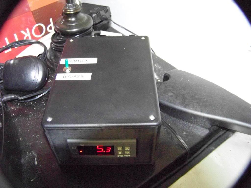
9. Close up the box and place the Bypass Switch into the Center (off) position.
Setting your new Temperature controller up for use.
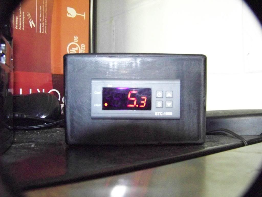
Plug the Controller into the wall outlet. It’s ok if the STC-1000 comes on as the Bypass switch is in the Center (off) position.
Plug the Refrigerator into the Cool Plug.
Plug your heat source, a reptile warmer works well as a low cost warmer, and place it inside the refrigerator.
Switch the Bypass to Bypass and the refrigerator should come on.
Program the STC-1000 per the instruction sheet.
Note: the STC-1000 is in Degrees C
Go Brew some Beer.
RDWAHAHB!!!!
Tools:
Cross Tip Screwdriver
Flat tip Screwdriver
Needle Nose Plyers
Wire Cutters
Wire Stripper (if you’re no good at stripping wire)
Drill with bits
Dremel with cutting and routing attachments
Soldering Iron
Solder
If you want to build one and have questions send a PM.
Cheers y'all,
I have seen numerous plans on the internet for these and have adapted this one from several of them. Since I’m using a refrigerator that won’t always be full of fermenting wort I’ve added a bypass switch to allow the fridge to work normally. As a heat source I'll be using an old heating pad.
Suppliers:
EBay:
STC-1000 Available from numerous sources (12 VDC, 110 VAC, 220 VAC) ranging from $15.00 to $25.00 US.
Radio Shack:
Project Enclosure $6.49 US
4 Position Terminal Block $2.49 US
Size N D/C input Plug and socket $10.00 US
10A / 125 AC SPDT Switch $8.00 US
Hook up wire, min 22 gauge, in 3 colors (lead, neutral and ground) $8.49 US
Lowes:
20 Amp Duplex Outlet with removable bridge $5.97 US
My total cost was $52.94. I picked up my STC-1000 for 19.99 with free shipping and I have a ton of PC Power Chords around and stripped my wires out of one.
Wiring Diagram.
This first diagram includes the bypass switch.
And without the bypass switch it would look like this
The controller used in this is the STC-1000 which is designed for use with Aquariums. Also it only reads in degrees C. The colors used for wires in the diagram are:
Black for the Load (P) black in the build
Blue for the Neutral (N) white in the build
Brown for Ground (G) green in the build
The A/C in is a 3 prong plug in like you would find on any computer. The wires off of this go into a Terminal Block.
From the Terminal Block the wires go out to:
Positive (P) 4 wires out
Connector 1, the STC-1000 power positive connector
Connector 5, the Cool In
Connector 7, the Heat In
Connection on the Bypass side of the SPDT switch.
Neutral (N) 2 wires out:
Connector 2, Power negative connector
Negative (silver) connector on the outlet
Ground (G) connects to the outlet ground connection
This leaves connections 3, 4, 6 and 8 on the STC-1000 unconnected.
Connections 3 and 4 are for the Temperature sensor.
Connection 6 will go to control side of the switch if you’re using the Bypass or the Positive side of the Cool plug if not.
Connection 8 will go to the positive side of the Heat plug.
If using the Bypass Switch, the center position connector from the switch is then wired to the Positive side of the cool plug on the outlet.
Parts that don’t have screw mounts, such as the Terminal block, can be hot glued to the box.
Steps:
1. Mark the positions for the cuts to be made into the case for parts mounting.
2. Cut and shape the holes. I used a Dremel and it was really simple. If you had to use a Craft Knife it could be done but would be tough going and time consuming.
3.Remove the bridge from the Hot (Brass) side of the Duplex Plug and mount it, the Sensor Plug socket and the STC – 1000 and drill the holes for the screws where needed.
4. Solder wires to the 3 posts on the A/C input, sensor plug and socket and bypass switch if you’re using one.
5. Attach wires from Sensor Plug socket to the STC – 1000 (3 and 4).
6. Run wires from A/C input to the Terminal Block.
7. Run wires from the Terminal Block (P) to the STC – 1000 (1, 5, 7), Bypass Switch (Bypass) and the Duplex Plug (N, G).
8. Run the wires from the Bypass Switch (Control) to the STC – 1000(6), Bypass Switch (Center) to the Duplex Plug Cool side and from the STC – 1000(8) to the Positive side of the Heat plug.
Note: If you’re not using the Bypass Switch then the wire from Connection 6 (Cool Switch) on the STC – 1000 will connect directly to the Positive side of the Cool Plug.
9. Close up the box and place the Bypass Switch into the Center (off) position.
Setting your new Temperature controller up for use.
Plug the Controller into the wall outlet. It’s ok if the STC-1000 comes on as the Bypass switch is in the Center (off) position.
Plug the Refrigerator into the Cool Plug.
Plug your heat source, a reptile warmer works well as a low cost warmer, and place it inside the refrigerator.
Switch the Bypass to Bypass and the refrigerator should come on.
Program the STC-1000 per the instruction sheet.
Note: the STC-1000 is in Degrees C
Go Brew some Beer.
RDWAHAHB!!!!
Tools:
Cross Tip Screwdriver
Flat tip Screwdriver
Needle Nose Plyers
Wire Cutters
Wire Stripper (if you’re no good at stripping wire)
Drill with bits
Dremel with cutting and routing attachments
Soldering Iron
Solder
If you want to build one and have questions send a PM.
Cheers y'all,