Is it ok to use paint thinner instead of acetone for cleaning up the dimple and coupler before soldering?
You are using an out of date browser. It may not display this or other websites correctly.
You should upgrade or use an alternative browser.
You should upgrade or use an alternative browser.
Soldering Stainless steel
- Thread starter BargainFittings
- Start date

Help Support Homebrew Talk:
This site may earn a commission from merchant affiliate
links, including eBay, Amazon, and others.
wyzazz
Well-Known Member
Is it ok to use paint thinner instead of acetone for cleaning up the dimple and coupler before soldering?
Nope, use acetone or laquer thinner. Even iso alcohol would be better than paint thinner.
CoalCracker
Well-Known Member
I used MEK and that worked fine.
Because of the longer tapered threads, there is a gap between the box and the coupling. It would need to be snugged up. I just went out and was going to see if the locknut I have would fit in the gap but my garage is so messy from all of this stuff that couldn't find it right now.
I guess I still don't get how kal's electric box setup wouldn't work. I plan on using it with a 1" welding spud, and it seems like it would be pretty snug.
jsguitar
Well-Known Member
I guess I still don't get how kal's electric box setup wouldn't work. I plan on using it with a 1" welding spud, and it seems like it would be pretty snug.
You may have missed that I'm using an unusual NPT threaded element instead of the usual NPS. The NPT threads are tapered and seal with the threads unlike the NPS which threads all the way down and seals with the gasket. That's what allows the box to be secured tight against the kettle. I'm assuming you're using a water heater element, in which case it will work perfectly (I think).
With my element, even when screwed all the way in, there's a big gap between the box and the coupling that leaves the box wobbling around. Here's the thread dealing with my NPT elements. I'm still having a little trouble getting this solution to work on my HLT.
https://www.homebrewtalk.com/f170/316ss-4500w-elements-ebay-369999/index3.html
ETA: Also, they're too long which is why I'm using the coupling.
wyzazz
Well-Known Member
Try going to Lowe's/Home Depot and picking up some washers or even a piece of Spa-Flex or other tubing that can take up the gap. That might allow the Kal method to work for you.


$10.99 ($31.16 / Ounce)
Hornindal Kveik Yeast for Homebrewing - Mead, Cider, Wine, Beer - 10g Packet - Saccharomyces Cerevisiae - Sold by Shadowhive.com
Shadowhive


$176.97
1pc Commercial Keg Manifold 2" Tri Clamp,Ball Lock Tapping Head,Pressure Gauge/Adjustable PRV for Kegging,Fermentation Control
hanhanbaihuoxiaoshoudian


$82.50
Wilbur Curtis Brew Cone Assembly with Splash Pocket, High Volume - Commercial-Grade Brew Basket - WC-3422 (Each)
Global Commercial Parts


$7.79 ($7.79 / Count)
Craft A Brew - LalBrew Voss™ - Kveik Ale Yeast - For Craft Lagers - Ingredients for Home Brewing - Beer Making Supplies - (1 Pack)
Craft a Brew


$53.24
1pc Hose Barb/MFL 1.5" Tri Clamp to Ball Lock Post Liquid Gas Homebrew Kegging Fermentation Parts Brewer Hardware SUS304(Gas MFL)
yunchengshiyanhuqucuichendianzishangwuyouxiangongsi


![Craft A Brew - Safale S-04 Dry Yeast - Fermentis - English Ale Dry Yeast - For English and American Ales and Hard Apple Ciders - Ingredients for Home Brewing - Beer Making Supplies - [1 Pack]](https://m.media-amazon.com/images/I/41fVGNh6JfL._SL500_.jpg)
$6.95 ($17.38 / Ounce)
$7.47 ($18.68 / Ounce)
Craft A Brew - Safale S-04 Dry Yeast - Fermentis - English Ale Dry Yeast - For English and American Ales and Hard Apple Ciders - Ingredients for Home Brewing - Beer Making Supplies - [1 Pack]
BellaRae


$58.16
HUIZHUGS Brewing Equipment Keg Ball Lock Faucet 30cm Reinforced Silicone Hose Secondary Fermentation Homebrew Kegging Brewing Equipment
xiangshuizhenzhanglingfengshop


$22.00 ($623.23 / Ounce)
AMZLMPKNTW Ball Lock Sample Faucet 30cm Reinforced Silicone Hose Secondary Fermentation Homebrew Kegging joyful
无为中南商贸有限公司

$53.24
1pc Hose Barb/MFL 1.5" Tri Clamp to Ball Lock Post Liquid Gas Homebrew Kegging Fermentation Parts Brewer Hardware SUS304(Gas Hose Barb)
Guangshui Weilu You Trading Co., Ltd


$33.99 ($17.00 / Count)
$41.99 ($21.00 / Count)
2 Pack 1 Gallon Large Fermentation Jars with 3 Airlocks and 2 SCREW Lids(100% Airtight Heavy Duty Lid w Silicone) - Wide Mouth Glass Jars w Scale Mark - Pickle Jars for Sauerkraut, Sourdough Starter
Qianfenie Direct


$45.74 ($45.74 / Count)
Brewer's Best Home Brew Beer Ingredient Kit - 5 Gallon (Grapefruit IPA)
Amazon.com


Ah guess I did miss that
Hey guys, I learned how to do this somewhere in this thread but I don't know if anyone's made a concise post about it yet. ")
I was successful soldering in a 2" triclamp ferrule into the side of a keggle. I first drilled a 1 7/8" hole with a hole saw from the hardware store, and then flared it out with a custom tool I made on the lathe:
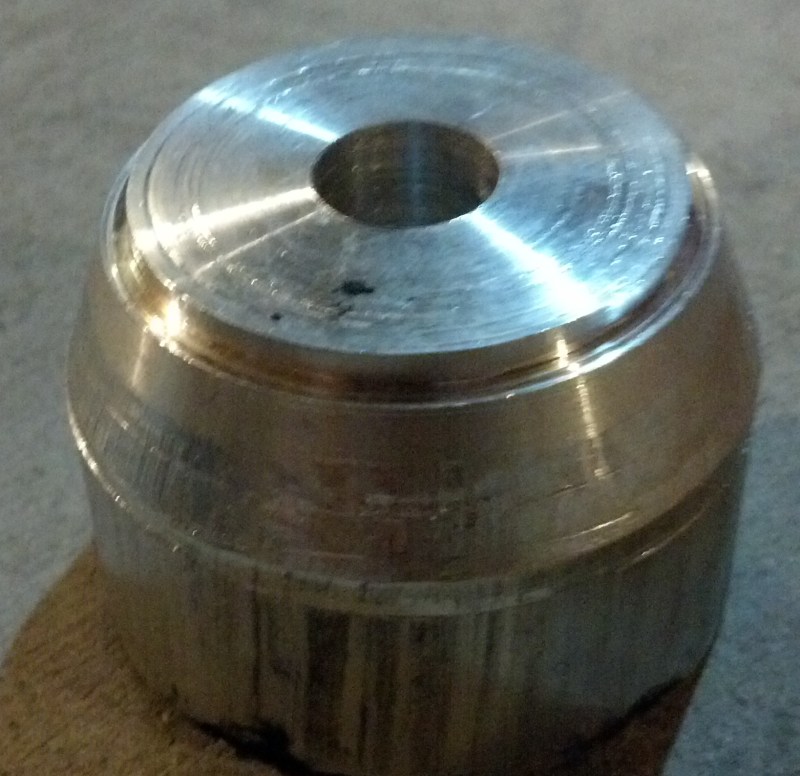
(It's a 15degree taper from 1.75" to 2.020")
I pulled that through with a 1/2-20 grade 8 bolt/nut with a 2" PVC coupler for the outside. Don't discount the importance of a) the fine thread bolt and b) the grade 8 hardware because it takes surprising force to make the dimple.
Once the dimple was formed I tapped in the 2" triclover nipple and soldered with stainless flux from McMaster and standard lead free solder from Menards:
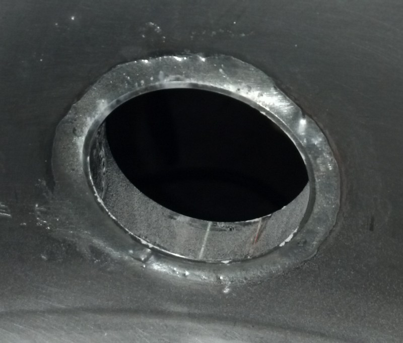
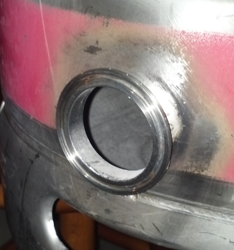
I then used the element adapter kit from StillDragon to complete the install of your standard Camco element.
This approach makes it really easy to take the element out for cleaning, and also avoids the issue of threading an NPS element into a 1" NPT coupler.
I hope this helps someone out there!
I was successful soldering in a 2" triclamp ferrule into the side of a keggle. I first drilled a 1 7/8" hole with a hole saw from the hardware store, and then flared it out with a custom tool I made on the lathe:
(It's a 15degree taper from 1.75" to 2.020")
I pulled that through with a 1/2-20 grade 8 bolt/nut with a 2" PVC coupler for the outside. Don't discount the importance of a) the fine thread bolt and b) the grade 8 hardware because it takes surprising force to make the dimple.
Once the dimple was formed I tapped in the 2" triclover nipple and soldered with stainless flux from McMaster and standard lead free solder from Menards:
I then used the element adapter kit from StillDragon to complete the install of your standard Camco element.
This approach makes it really easy to take the element out for cleaning, and also avoids the issue of threading an NPS element into a 1" NPT coupler.
I hope this helps someone out there!
wyzazz
Well-Known Member
Hey guys, I learned how to do this somewhere in this thread but I don't know if anyone's made a concise post about it yet.
I was successful soldering in a 2" triclamp ferrule into the side of a keggle. I first drilled a 1 7/8" hole with a hole saw from the hardware store, and then flared it out with a custom tool I made on the lathe:
(It's a 15degree taper from 1.75" to 2.020")
I pulled that through with a 1/2-20 grade 8 bolt/nut with a 2" PVC coupler for the outside. Don't discount the importance of a) the fine thread bolt and b) the grade 8 hardware because it takes surprising force to make the dimple.
Once the dimple was formed I tapped in the 2" triclover nipple and soldered with stainless flux from McMaster and standard lead free solder from Menards:
I then used the element adapter kit from StillDragon to complete the install of your standard Camco element.
This approach makes it really easy to take the element out for cleaning, and also avoids the issue of threading an NPS element into a 1" NPT coupler.
I hope this helps someone out there!
Very nice! I've been thinking of doing the very same thing.
I did something similar, but take the post above's advice as he didnt make the mistakes I did.
I used a 1 1/4" conduit punch (~1.75" hole), which meant a bigger dimple. I also used a custom made tool but had it made to exactly 2". With the flex of the larger dimple this left me with a hole a fair bit too small. It took alot of grinding/hammering to get it in place.
If you can... start with a hole that is closer to 2" (but not too close), and use a tool that allows for you to go slightly larger then 2". It will save yourself alot of grief.
Everbody has a different take on this, so I thought I throw out mine.
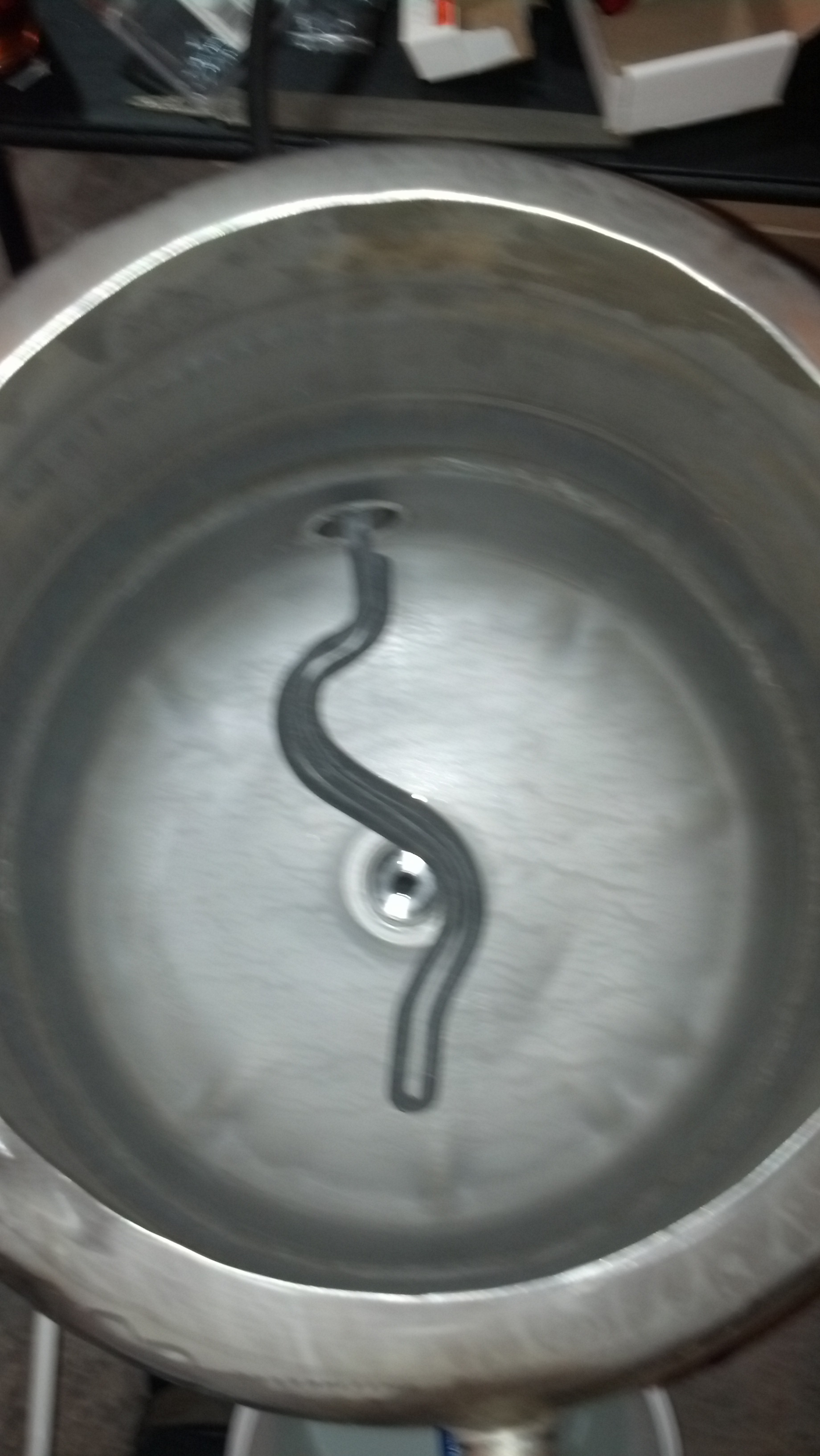
I'm way to cheap to buy anything, so I built a dimple maker out of 2 sockets and bolt.
Drilled a 1/2" hole with a step bit, pulled the dimple, and ran 3/4 ridged copper pipe through and soldered.
Attach fitting of your choice to pipe.
13mm kobalt 1/2 drive socket makes the dimple
24mm socket, bolt, washers, nut yada yada yada
don't pull it all the way through it will be too loose

This seems like a really good idea - has anyone else tried it? I was just about to pull the trigger on purchasing various concentric reducing couplers, etc... when I saw this. Would appreciate feedback from anyone who has used sockets to flare holes before I give it a try...
I've been lurking and learning on HBT for more than a month now, and have learned great deal on many interesting threads, but this one takes the cake. I've just reached the last post after reading everything through from end to end, and even after more than 1000 posts, there was still more new and useful information.
I'm kind of google-eyed and realize that I am the only one to post on this thread in the new year so far, but I have a couple questions in case anyone out there with expertise is still monitoring this thread:
1/4" WELDING SPUDS: I want to use 1/4" compression fittings for my thermo probes and want no protrusion into the interior cavity (other than the probe). From what others have done, it sounds like a 1/4" half coupler welding spud is what I want to use. Specific questions I am still not clear on:
-is there any reason to dimple the hole for these fittings? From what I read, the 1/2" half couplers can just be laid on a circular bed of solder and allowed to melt down into a bead by heat and gravity - any reason that this would not also be the best way to solder on the 1/4" half-couplers as well?
-one advantage of dimpling the hole is that the spud is held in place. If it is better not to dimple for a 1/4" thermoprobe fitting, what size hole should be cut and how do you assure that the fitting remains centered on the hole while heating?
LEVEL GUAGE: When you solder on a half-coupler for use with a level guage, is anything usually done in advance to position the coupler so that an elbow will screw in to the correct orientation (vertical)? This should be an issue with any welded fitting for use with a level guage - is there always enough slack to get a tight seal oriented vertically (with Teflon tape) or is there something that should be done to predetermine the ideal 12 o'clock position on the spud before welding/soldering?
TRICLOVER FERRULES: It seems that welders generally shy away from trying to weld the short 1/2" (12.7mm) triclover ferrules because it is too tight for them to work. With dimpling and soldering it should be no more difficult to solder on the shorter ferrules - has any one done this? Is there any downside (not enough space for the clamp, etc...)??
My list of questions would have been sooooo much longer only a few short days ago.....
Thanks for everyone who has contributed to this thread in the past anyone still monitoring that can help me with the above questions before I try my first joints.
-fafrd
wyzazz
Well-Known Member
user 42322
Well-Known Member
- Joined
- Aug 17, 2009
- Messages
- 64
- Reaction score
- 2
fafrd said:TRICLOVER FERRULES: It seems that welders generally shy away from trying to weld the short 1/2" (12.7mm) triclover ferrules because it is too tight for them to work. With dimpling and soldering it should be no more difficult to solder on the shorter ferrules - has any one done this? Is there any downside (not enough space for the clamp, etc...)??
I soldered short ferrules into my kettle. Clearance with the wings on the clamp can be tight depending on orientation, but I don't find it to be an issue. I dimpled outward and pushed the ferrules in by hand though (which was a pain). If you dimpled inward it might put the flange too close to the kettle wall.
I soldered short ferrules into my kettle. Clearance with the wings on the clamp can be tight depending on orientation, but I don't find it to be an issue. I dimpled outward and pushed the ferrules in by hand though (which was a pain). If you dimpled inward it might put the flange too close to the kettle wall.
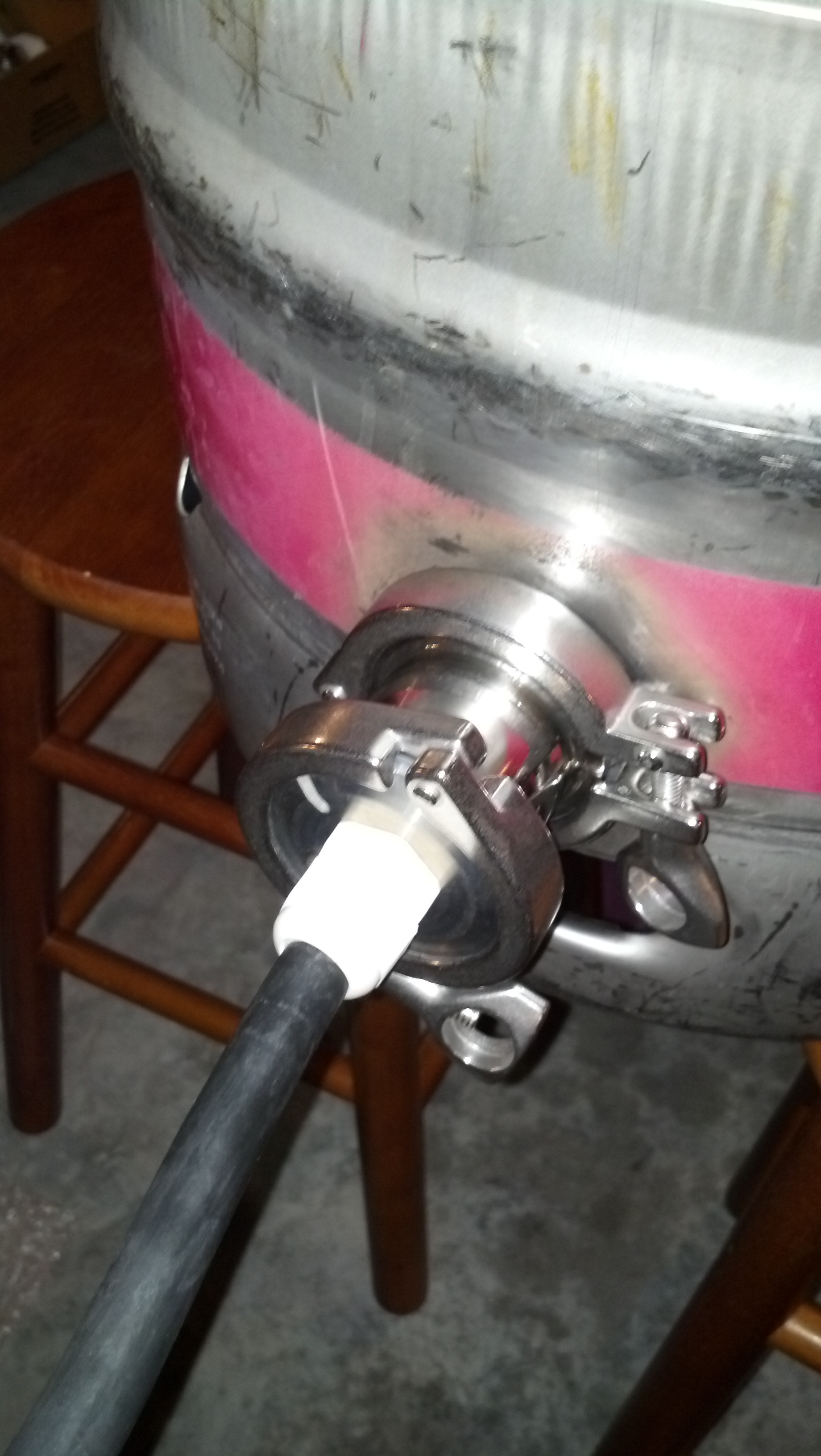
Same for me. You can see pictures of my setup up a few posts, the last pic shows that there's not much clearance there between the clamp and the wall, but the curvature of the vessel helps.

wyazz, yes, my bad - sorry. I'd seen the half-couplings and reading through all the many posts on this thread, guess I interpreted references to 'welding spuds' to be talking about the same thing. I am planning to use 1/4" half couplings - NOT welding spuds.
Thanks for helping me to clarify. And understand that true spuds CANNOT be dimpled and that half-couplings CAN be dimpled. My remaining question is whether there is an advantage (or a drawback) to dimpling a 1/4" half-coupling versus just letting the half-coupling sink down into a bed of solder on the outer surface of the vessel?
And also have an additional question after thinking things over last night: If the half-coupling can be effectively soldered onto the outer surface, is there any reason that the hole cannot be drilled after the half-coupling has been soldered? This would be for a temperature probe.
Great to see that people like you are still monitoring this thread and contributing!
-fafrd
I soldered short ferrules into my kettle. Clearance with the wings on the clamp can be tight depending on orientation, but I don't find it to be an issue. I dimpled outward and pushed the ferrules in by hand though (which was a pain). If you dimpled inward it might put the flange too close to the kettle wall.
Thanks - my orientation will be out from the middle of the bottom surface of the Mash Tun for a bottom drain, so I suppose this would be the worst case as far as orientation, right? For this situation would you recommend going with one of the 1" length ferrules?
Also, I saw in one thread where they filed down the 'corners' of the end of the tube on the ferrule so that it would be easier to 'pull' back into the kettle after the dimple had been made outwards - is this how you did it? Was it a pain because you had to taper the end of the ferrule or despite that?
I'm also considering putting a separate 1" ferrule out from the side as close to the bottom as possible. This would be for a removable foldback heating element and so I would need to use a short ferrule because of the foldback. In this case, the clamp has full clearance from below because you are below the bottom of the vessel. Would you have any concerns about this configuration? How close to the bottom surface of the kettle do you believe the ferrule could be placed? With dimpling, it seems like you should be able to get the ferrule just above the bottom surface. From your experience, would you have any concerns about this position and orientation?
I'm debating the soldered-on-one-inch-nut idea as well, but it seems like for a fold-back element and wanting to get the element placed as close to the bottom surface of the vessel as possible, the tri-clover ferrule offers the greatest flexibility (as well as being easily removable).
thanks again,
-fafrd
Same for me. You can see pictures of my setup up a few posts, the last pic shows that there's not much clearance there between the clamp and the wall, but the curvature of the vessel helps.
So do you think that coming off of the center of the bottom of the vessel for a bottom drain (flat surface - no curvature) that there would not be enough clearance to get the clamp in place with a short ferrule?
I just wanted to thank everyone who posted to this thread. I learned a lot an was able to pull a dimple and solder two couplings yesterday. Great info for someone who has never done work like this before. Cheers.��
View attachment 94726
Hockypuck,
for someone who has never done work like this before, those are damn nice-looking joints!!!

I'm hoping to follow in your footsteps soon (though I have some silver soldering of brass onto stainless 20 years ago
Looks like you did 1/2" full couplings - can I ask how long it took you to do both couplings as a 'virgin'?
Also, did you purchase the recommended concentric couplers to make your dimpling tool or do something different? I am thinking about trying the idea of using sockets that was posted a few pages back...
-fafrd
p.s. and one more question - I suspect that you probably purchased the recommended solder and flux, but since some have apparently been successful using standard unleaded plumbing solder, I just wanted to ask what solder and flux you used for these joints....
and while on the subject of additional details, what did you use to cut your holes (step bit or hole saw)?
wyzazz
Well-Known Member
My remaining question is whether there is an advantage (or a drawback) to dimpling a 1/4" half-coupling versus just letting the half-coupling sink down into a bed of solder on the outer surface of the vessel? Dimpling allows for a mechanical bond as well as the soldering bond that is created. It is stronger than just soldering the fitting on to the metal.
And also have an additional question after thinking things over last night: If the half-coupling can be effectively soldered onto the outer surface, is there any reason that the hole cannot be drilled after the half-coupling has been soldered? This would be for a temperature probe. You have a higher likelihood of marring your threads inside the coupler. JMO
Hope that helps.
wyazz,
thanks for the feedback.
I know that dimpling makes the joint stronger mechanically, but for a temperature probe I don't think this extra mechanical strength would be needed. Unless there is a fear that the coupling would fall off, soldering down onto the surface should be strong enough (as several others have apparently done) - is there something more I am missing?
And as far as marring threads when drilling AFTER soldering, that would be my concern as well. On the other hand, the hole would only be drilled to the ID of the pips while the threads only extend in to the OD of the pipe. For example, with the 1/4" half-coupler I am planning to use, a 1/4" (0.25") hole would need to be drilled into the center of a coupling whose threads only extend to within about 0.460", so there would be close to 1/8" of clearance between the outside edge of a 1/4" drill bit and the threads of the coupling. Of course, you could not use a step bit and you would want to keep the 1/4" bit from rattling around, so starting with a good center punch would seem to be mandatory and it may also be a good idea to start with a small pilot hole... Thoughts?
There are two things I find attractive about both of these ideas:
1/ minimum disruption to sidewall of vessel - the hole is as small as possible and causes minimum deformation to the sidewall (versus dimpling, for example).
2/ self-aligning (no risk of the half-coupling soldering down off-center versus a pre-drilled hole).
I may make a practice joint like this on my keg top and see how well it works...
-fafrd
fafrd said:Hockypuck,
for someone who has never done work like this before, those are damn nice-looking joints!!!
I'm hoping to follow in your footsteps soon (though I have some silver soldering of brass onto stainless 20 years ago
Looks like you did 1/2" full couplings - can I ask how long it took you to do both couplings as a 'virgin'?
Also, did you purchase the recommended concentric couplers to make your dimpling tool or do something different? I am thinking about trying the idea of using sockets that was posted a few pages back...
-fafrd
p.s. and one more question - I suspect that you probably purchased the recommended solder and flux, but since some have apparently been successful using standard unleaded plumbing solder, I just wanted to ask what solder and flux you used for these joints....
and while on the subject of additional details, what did you use to cut your holes (step bit or hole saw)?
FAFRD,
Thanks for the response. I did use full couplings. The longest part of the process was drilling a hole. I used a self tapping step bit I got from amazon. The dimpling tool was the recommended tapered 3/4-1/2" coupling with the larger coupling. I did have to use a half inch bolt and a crap load of washers instead of the recommended 5/8" bolt and it worked just fine. One dimple took longer than the other. Be careful to check the size of your coupler against the size of your taper. The first time I did it I pulled the taper all the way through and it ended up being too large of a hole to hold the 1/2" coupler. I ended up using a hammer to pound the hold back down to where I could draw the coupling into it securely. The soldering took minutes. Overall I'd say it only took two hours total including sanding and filing. A dremel helps with the cleanup. I used a small kit of the Harris stay brite flux that came with small gauge solder.Found it at my local airgas for $12. I tried both making a ring of solder and just heating and touching and found the touching worked better than trying to rely on the ring of solder to spread properly on its own. The heat/touch allowed me more control. Have fun. I'm glad I finally did it.
DrPhilGood
Well-Known Member
Been reading this thread for awhile now and I am starting to order the parts for my dimple tool but I can not for the life of me find 9/16" bolts fully threaded...anywhere. I've searched lowes/home depot/ and no where on mcmaster carr. I even tried the metric equivalent (m14?) with no luck. Any help here? Part number? Thanks guys!
wyzazz
Well-Known Member
I know that dimpling makes the joint stronger mechanically, but for a temperature probe I don't think this extra mechanical strength would be needed. Unless there is a fear that the coupling would fall off, soldering down onto the surface should be strong enough (as several others have apparently done) - is there something more I am missing? I have banged my kettle around pretty well after a brewday & those fittings stick out a bit, I want them to be as strong as possible. You can solder perfectly fine without dimpling, but dimpling makes it stronger. I like the extra reassurance.
DrPhilGood said:Been reading this thread for awhile now and I am starting to order the parts for my dimple tool but I can not for the life of me find 9/16" bolts fully threaded...anywhere. I've searched lowes/home depot/ and no where on mcmaster carr. I even tried the metric equivalent (m14?) with no luck. Any help here? Part number? Thanks guys!
I used a 1/2" bolt with no problems.
I have banged my kettle around pretty well after a brewday & those fittings stick out a bit, I want them to be as strong as possible. You can solder perfectly fine without dimpling, but dimpling makes it stronger. I like the extra reassurance.
OK - thanks. I guess if I ever knock one of these of I can always dimple and re-solder, right? For a temperature probe, I like the idea of a minimum-sized hole in the vessel wall if it can be strong enough...
FAFRD,
Thanks for the response. I did use full couplings. The longest part of the process was drilling a hole. I used a self tapping step bit I got from amazon. The dimpling tool was the recommended tapered 3/4-1/2" coupling with the larger coupling. I did have to use a half inch bolt and a crap load of washers instead of the recommended 5/8" bolt and it worked just fine. One dimple took longer than the other. Be careful to check the size of your coupler against the size of your taper. The first time I did it I pulled the taper all the way through and it ended up being too large of a hole to hold the 1/2" coupler. I ended up using a hammer to pound the hold back down to where I could draw the coupling into it securely. The soldering took minutes. Overall I'd say it only took two hours total including sanding and filing. A dremel helps with the cleanup. I used a small kit of the Harris stay brite flux that came with small gauge solder.Found it at my local airgas for $12. I tried both making a ring of solder and just heating and touching and found the touching worked better than trying to rely on the ring of solder to spread properly on its own. The heat/touch allowed me more control. Have fun. I'm glad I finally did it.
Thanks for these additional details. So getting the holes cut right, dimpled, and smooth sounds like the long pole in the tent versus the actual soldering. Someone pointed out that cutting the holes with a stepping bit amounts to cutting 4 or 5 holes. If you had to do another joint would you try a hole saw or were you happy enough with the stepping bit? (I have not yet bought my bits)
And when you say two hours was that an hour per hole (two hours for both holes) or two hours per hole (4 hours for both holes)?
I've done some silver soldering using the 'heat and touch' method, so given your experience, I will probably try that technique for my first attempt...
I assume you have a socket set - would you think that using sockets to make a dimple tool would work as well as the fittings you used or is there a reason you think the coupler you used was more effective than a socket-based tool would have been?
-fafrd
fafrd said:Thanks for these additional details. So getting the holes cut right, dimpled, and smooth sounds like the long pole in the tent versus the actual soldering. Someone pointed out that cutting the holes with a stepping bit amounts to cutting 4 or 5 holes. If you had to do another joint would you try a hole saw or were you happy enough with the stepping bit? (I have not yet bought my bits)
And when you say two hours was that an hour per hole (two hours for both holes) or two hours per hole (4 hours for both holes)?
I've done some silver soldering using the 'heat and touch' method, so given your experience, I will probably try that technique for my first attempt...
I assume you have a socket set - would you think that using sockets to make a dimple tool would work as well as the fittings you used or is there a reason you think the coupler you used was more effective than a socket-based tool would have been?
-fafrd
I'm a cheap ass so I'd probably stick with my step bit when I do my third keg. The holes became slower to cut when I got closer to the final size I needed for some reason. I'd say the first coupling took about an hour an a half while I was figuring it out as I went and being extra careful. Once I knew what I was doing I flew through the next hole in about half an hour. I haven't read the part about the sockets. I do however think the tapered coupler is a more gradual way to open the steel and ward off any tearing in the metal. I'm not even sure if this is something to be concerned about but whatever. Cheers.
Similar threads
- Replies
- 41
- Views
- 4K
- Replies
- 0
- Views
- 2K
