• Please visit and share your knowledge at our sister communities:
  • If you have not, please join our official Homebrewing Facebook Group!

    Homebrewing Facebook Group

Simple Control Panel w/ Illuminated Switches

Homebrew Talk

Help Support Homebrew Talk:

This site may earn a commission from merchant affiliate links, including eBay, Amazon, and others.

mattman7000

Member
Joined
Jun 28, 2014
Messages
13
Reaction score
0
Location
Longview
Hello Everyone!
I'm fairly new at brewing and trying to get my own version of a simple e-HERMS set up in my garage. It's a small scale set up. My BK is only 5 gal. and has a 120v heating element in it.
So, I've got almost everything together for this thing, but I'm stuck on the control panel. Like a lot of people here, I got my inspiration for the small set up from jkarp and his Countertop Brutus. I've purchased the same Auber PID, SSR, heat sink, and thermocouple (the 40A like he lists in his parts chart). I've also downloaded the instruction manual from Auber and been all through these forums and the Electric Brewery website. What I'm having trouble with is designing a control panel w/ a little more in the box than just the PID. I like jkarps idea of the 120v switch/plug combo, but wanted to take it a step further by having the plug controlled by an illuminated switch. As I started getting more and more into the forums on how to do this, I've become more and more confused. Essentially what I would like to configure is a simple control panel with a main power illuminated switch, an illuminated switch for an outlet that I can plug my march pump into, a third switch for an outlet I can plug my analog timer into (the timer looks like this one: http://www.ebay.com/itm/GraLab-Dark...446?pt=LH_DefaultDomain_0&hash=item56684e4d06), and a fourth switch for the PID/element. It's probably overkill for a system like mine, but I thought it would be best to try and have all the wiring go to one box instead of trying to run extension cords all over my garage to different outlets. Here is a link to the switches I was thinking about: http://www.auberins.com/index.php?main_page=product_info&cPath=7_32&products_id=223

Anyways, is this all a dumb idea? Would anyone out there be willing to help me figure out how to wire this thing. I'm really new at electric wiring and want to be sure I'm doing everything correctly and safe. I thought about just getting a power strip and plugging everything in there, but I don't know how safe that would be either.:(
 
Most of the illuminated switches that Auber (and others) sell are capable of handling the amperage draw that your pump and timer will handle, so you literally just wire the hot leg through the switch (NO switch block) and to your outlet. I would skip the switch for the PID - you've got the main on/off switch for the panel - when are you going to want to have the panel on but the PID off? As for the main power switch - you'll probably need to use a contactor (a big realy) that the illuminated switch 'tuns on' to allow power to flow to the rest of the panel.

You're headed in the right direction.
 
The epic PJ diagram thread has all the info you need, including different diagrams and the components needed. You could start with the most basic diagram in that thread. You'll need to understand things like hot, neutral, ground....wiring gauge, wiring with 110v vs 220v, wire routing, good connections, panel layout, etc...

Its all do-able, with a certain learning curve. But once you do it, then you'll have the knowledge.

Can you use a program to draw a diagram of what your thinking? Even MS Paint could be used. Drawing a diagram is good for your own thinking, and gives people something to respond to.

Having a switch for every component isn't dumb....gives you maximum control. For example, I have a power switch for my Auber PID and one for the element. That way I can futz with the PID while the element isn't powered, preventing risk of dry-firing.

HTH
 
Having a switch for every component isn't dumb....gives you maximum control. For example, I have a power switch for my Auber PID and one for the element. That way I can futz with the PID while the element isn't powered, preventing risk of dry-firing.

HTH

Not bashing on you, but legitimately curious - do you ever turn off your PID while the panel is on? I totally get (and also have) the switch to turn off the element - the value of that has been repeatedly shown and discussed. I still don't know any situation where I'd want my main control panel on, but would feel the need to have the PID turned off. So I'm curious what purpose it serves.
 
Ok so I checked out the thread again for the PJ diagrams and several pages into it I found something that I think is close to what might work for me. Here is the link to that page from when I clicked on the image:

http://www.pjmuth.org/beerstuff/images/Auberin-wiring1-SYL-2352-basic5-RIMS.jpg

There are a couple of things I would like to change. First off, my PID is the SYL-2362 so does that make a difference in the diagram (other than the terminals on the back of the PID that I would connect everything to)? I also need to add an extra outlet and switch for the timer that I mentioned in my original post.
My other questions center around design elements. I was wondering, would be safer to use 2 position selector switches wired to indicator lights instead of the illuminated switches I had first wanted to go with? By safer I mean that with the selector switches it seems like there would be less chance of somebody (namely a clumsy brewer like myself) accidentally turning a selector switch as opposed to bump up against and activating an illuminated switch. What do you guys think?
Also, I see a lot of people have those little flashing buzzer alarms hooked to their PIDs. Is this necessary? This may seem dumb, but does the PID make noise without a buzzer installed? Auber has them for cheap anyways, but I wouldn't know quite how to install it.
Lastly, is there a contactor you guys would recommend?
Thanks again for the help everyone! The information is truly invaluable to me, so the next time any of you happen to be along the great Columbia in the Pacific Northwest drop me a line and we can go share a couple of cold ones. Cheers!
 
Not bashing on you, but legitimately curious - do you ever turn off your PID while the panel is on? I totally get (and also have) the switch to turn off the element - the value of that has been repeatedly shown and discussed. I still don't know any situation where I'd want my main control panel on, but would feel the need to have the PID turned off. So I'm curious what purpose it serves.

Pretty minor reason. The gfci breaker to my panel is in another room. When I'm done brewing I switch the pid off. I don't always go to the other room to shut off power to the panel. Not sure if I need to, in theory the panel getting power 24/7 doesnt hurt anything. But I agree, not a have-to-have.
 
Ok so I checked out the thread again for the PJ diagrams and several pages into it I found something that I think is close to what might work for me. Here is the link to that page from when I clicked on the image:

http://www.pjmuth.org/beerstuff/images/Auberin-wiring1-SYL-2352-basic5-RIMS.jpg

There are a couple of things I would like to change. First off, my PID is the SYL-2362 so does that make a difference in the diagram (other than the terminals on the back of the PID that I would connect everything to)? I also need to add an extra outlet and switch for the timer that I mentioned in my original post.
My other questions center around design elements. I was wondering, would be safer to use 2 position selector switches wired to indicator lights instead of the illuminated switches I had first wanted to go with? By safer I mean that with the selector switches it seems like there would be less chance of somebody (namely a clumsy brewer like myself) accidentally turning a selector switch as opposed to bump up against and activating an illuminated switch. What do you guys think?
Also, I see a lot of people have those little flashing buzzer alarms hooked to their PIDs. Is this necessary? This may seem dumb, but does the PID make noise without a buzzer installed? Auber has them for cheap anyways, but I wouldn't know quite how to install it.
Lastly, is there a contactor you guys would recommend?
Thanks again for the help everyone! The information is truly invaluable to me, so the next time any of you happen to be along the great Columbia in the Pacific Northwest drop me a line and we can go share a couple of cold ones. Cheers!

Its pretty hard to accidently push those button switches. Guess you could order them and see for yourself. Also its not like your pushing buttons all throuhout your brew session.

Wiring for the 2362 is probably tje same, but download and read the informative pdf....you'll need it for reference.

Pids dont typically have a built in alarm. No you dont have to have one, but helpfull for reaching mash in temps and approaching boil (prevent boil over).

Auberins and ebrew supply should have the contactors.
 
By the way, thank you very much to PJ for the inspiration and well thought out diagrams. They have helped me very much! I was wondering if it would be ok for me to copy and paste one of them into paint and then add the components I've been mentioning in this thread to the image and repost it so you guys can tell me if the wiring I'm thinking of is accurate. I don't know if that is the wrong thing to do or not because I certainly don't want to present PJs work as my own.
Please let me know if that is not ok to do. I will not attempt until I know one way or the other.
Thanks again everyone! Have a nice night
 
Pretty minor reason. The gfci breaker to my panel is in another room. When I'm done brewing I switch the pid off. I don't always go to the other room to shut off power to the panel. Not sure if I need to, in theory the panel getting power 24/7 doesnt hurt anything. But I agree, not a have-to-have.

Got it - so you don't have a main panel on/off switch - you kill power at the spa panel. I can get that. I've seen people with a panel on / off switch AND a PID on / off switch, and scratch my head.

:off: - back to the main discussion.
 
I don't know if that is the wrong thing to do or not because I certainly don't want to present PJs work as my own.
Please let me know if that is not ok to do. I will not attempt until I know one way or the other.

Can't speak for the man himself, but in my experience I don't think it'd be an issue. Just make sure you don't post it claiming it's yours, and give credit to the original source (both the designer, and who's panel / wiring diagram it's from). We're a community of sharing and caring individuals.

-Kevin
 
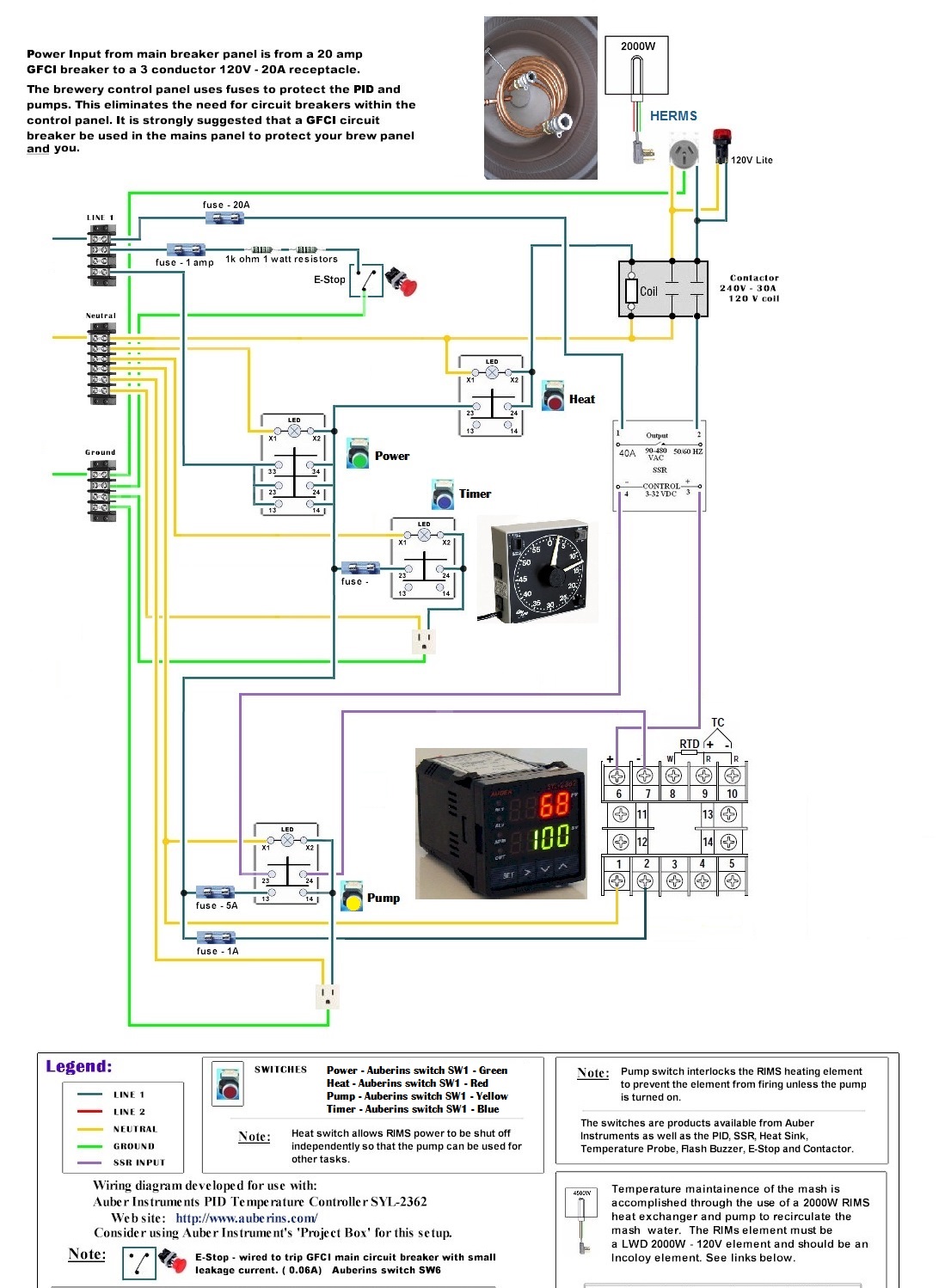
Ok, so here's a first draft. This image I pulled from a post by PJ in response to a member named MyNameIsPaul. I only changed a couple of things. I put in the SLY-2362, which is what I have at home. I tried to wire it the way the instructions said on the Auberins website. Next I changed it from a RIMS to a HERMS coil in my BK, which is where the element will be held. Then I added another box line on the power schematic (33, 34) which I attached the analog timer to.
So how does it look so far? I have a couple other changes to make, which I'll name in a later post. Let me know if anything is wrong with this drawing.

Control Panel.jpg
 
Now one of the things I was wondering about adding is a pump speed control. Dave Miller describes how to build one in his book "Brew Like A Pro" and he writes to use the Lutron FS-5F, or something equivalent. I was wondering if this item from Auber would work, here is the link:
http://www.auberins.com/index.php?main_page=product_info&cPath=2_30&products_id=353
I know that a lot of people on the forums don't like the idea of dialing down the pump and instead recommend regulating flow through ball valves. Does anyone have experience with a pump speed control? What does everybody recommend?

It depends upon what type of pump you have. I believe something like a DC solar pump would allow you to dial down the voltage, but a typical AC magnetic centrifugal pump will not. For that you want a ball valve, gate valve, or the like on the output side of the pump.
 
It depends upon what type of pump you have. I believe something like a DC solar pump would allow you to dial down the voltage, but a typical AC magnetic centrifugal pump will not. For that you want a ball valve, gate valve, or the like on the output side of the pump.

Not entirely true. It is true that voltage will not effect speed of an AC motor but freq will. Not sure it is worth the money to buy an AC motor speed controller when a $15 ball valve will do that same thing though.

That Auberlin device wont work for an AC motor.

The Lutron FS-5F just looks like a rheostat. again, not gonna work.

This would work
AC motor Speed control

TBO, as long as the pump is magnetically coupled, you can shut the valve without damage. the motor will just turn and the impeller wont.

Agreed, and the ball valves can be acquired for less than that. :)
 
Thanks for the input everyone. It's a March pump that I have. Has anybody read the book I'm talking about? I think Dave Miller actually uses one of these devices on his home brewery.
Does anybody know of an electrician that might be able to look at the schematic? I'm new to Washington state and haven't been able to find anybody in town
 
Good Morning! Bad News Brewery, I had a question about the contactor you mentioned that I should include as part of the main power assembly. I don't know if you've had a chance to look at the image I submitted of the PJ diagram I edited, but one thing he included in the original was a contactor coming off the SSR and heat switch. I didn't edit that out because I wasn't sure why PJ included it in the first place. I thought you could route the SSR directly to the element. I think I understand why your saying to put a contactor in the with the main power switch, but do you know why I would need one for the SSR?
 
You dont HAVE to have one. Many people connect thier SSRs to the element directly.(myself included) The reason people do it is for a second redudant safety on the heating element. IMHO, not needed.

It would be handy to have a switch that will turn the heating element off manualy, but you can put that switch in series with the control side of the SSR to turn it off,
 
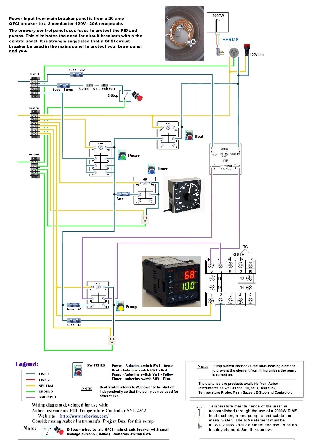
Alright, so here is a version of PJs diagram with my added components and the contactor removed. Does that look correct? One thing about the original diagram is that PJ has the SSR w/ direct connection to Line 1. Won't that supply power to the SSR w/o the power button actually being turned on? I could be way off on that, but I thought I would ask.

Control Panel - No Contactor After SSR.jpg
 
No, the line power on the SSR is fine, it wont pass voltage unless the SSR is on.

You need to change the heat switch though. That will do nothing when the SSR is on and it will power the element if the SSR if off. (More than likely melting the switch) The left input to the SSR (purple wire) is where you want the heat switch. After the pump switch. This will allow use of the pump even if the heat switch is off, and it will manually turn off the SSR. It will also turn off the SSR if the pump switch is off too

Like this

https://copy.com/suvNWDAtvHoSHmF9
 
Ooops, the heat switch isnt wired in series to control the power leg to the element.

I would keep the contactor. Its an absolute mechanical break to the element when the swith is off.
 
Also in terms of a pump control, ebay search for vortex fan controls. They have an on off switch and dial. Only about $25. These are designed for motors.

Out of curiosity, whats the purpose of the outlet connected to the analog timer?
 
Just a note: The Auberins switches SW1 are not capable of carrying more than 10 amps. That is the specific reason that I included a contactor in the original diagram. The 2000W 120V element draws 16.7 amps when powered on. The switch cannot handle that load.

Think about it.

Another note: I would not set up the pump with speed control. I really think that is a bad idea. Just saying.

P-J
Thank you for your notes and your design! Yeah the contractor is back in, no problem. I just didn't add the picture because it just goes back to the first image I posted on this thread.
So many people are telling me the pump speed control is a bad idea that I'm not going to experiment with that either. I just really Dave Miller's book and thought I'd see if anyone had tried out his design. A ball valve though will suit my needs just fine. Speaking if that, is best to situate that valve directly off the pump outlet, or can it be a valve just anywhere down stream of the pump?
On that first image where I added an outlet to your original design, did I do that correctly? Do you know what size fuse that would require?
Thanks again for your help to me and so many other people on this forum! It means a lot that you took the time to come up with those originals!
 
That timer probably pulls little power. A one amp fuse should be fine....you can always step up the fuse if needed.
 
Thank you for your notes and your design! Yeah the contractor is back in, no problem. I just didn't add the picture because it just goes back to the first image I posted on this thread.
So many people are telling me the pump speed control is a bad idea that I'm not going to experiment with that either. I just really Dave Miller's book and thought I'd see if anyone had tried out his design. A ball valve though will suit my needs just fine. Speaking if that, is best to situate that valve directly off the pump outlet, or can it be a valve just anywhere down stream of the pump?
On that first image where I added an outlet to your original design, did I do that correctly? Do you know what size fuse that would require?
Thanks again for your help to me and so many other people on this forum! It means a lot that you took the time to come up with those originals!
The valve can be anywhere down stream.
The fuse can be a 1 amp as the timer draws very little current.

Also - scrap the second diagram from your plans. It is not good...

Hope this helps you.

P-J
 
The valve can be anywhere downstream as long as there is no soft tubing (i.e. silicone) between the outlet of the pump and the valve that can't handle the pressure (I believe 8-9 psi for a March or Chugger pump) at the temperature of the liquid you'll be pumping.
 
The valve can be anywhere downstream as long as there is no soft tubing (i.e. silicone) between the outlet of the pump and the valve that can't handle the pressure (I believe 8-9 psi for a March or Chugger pump) at the temperature of the liquid you'll be pumping.

+1. IMO it is easiest to put the ball valve directly on the output of the pump, otherwise you will need hard plumbing between the pump and the ball valve. A quick disconnect after the ball valve is a good idea also, if you are using them.
 
Back
Top