
kfirestar1
Member
- Joined
- May 29, 2017
- Messages
- 15
- Reaction score
- 1
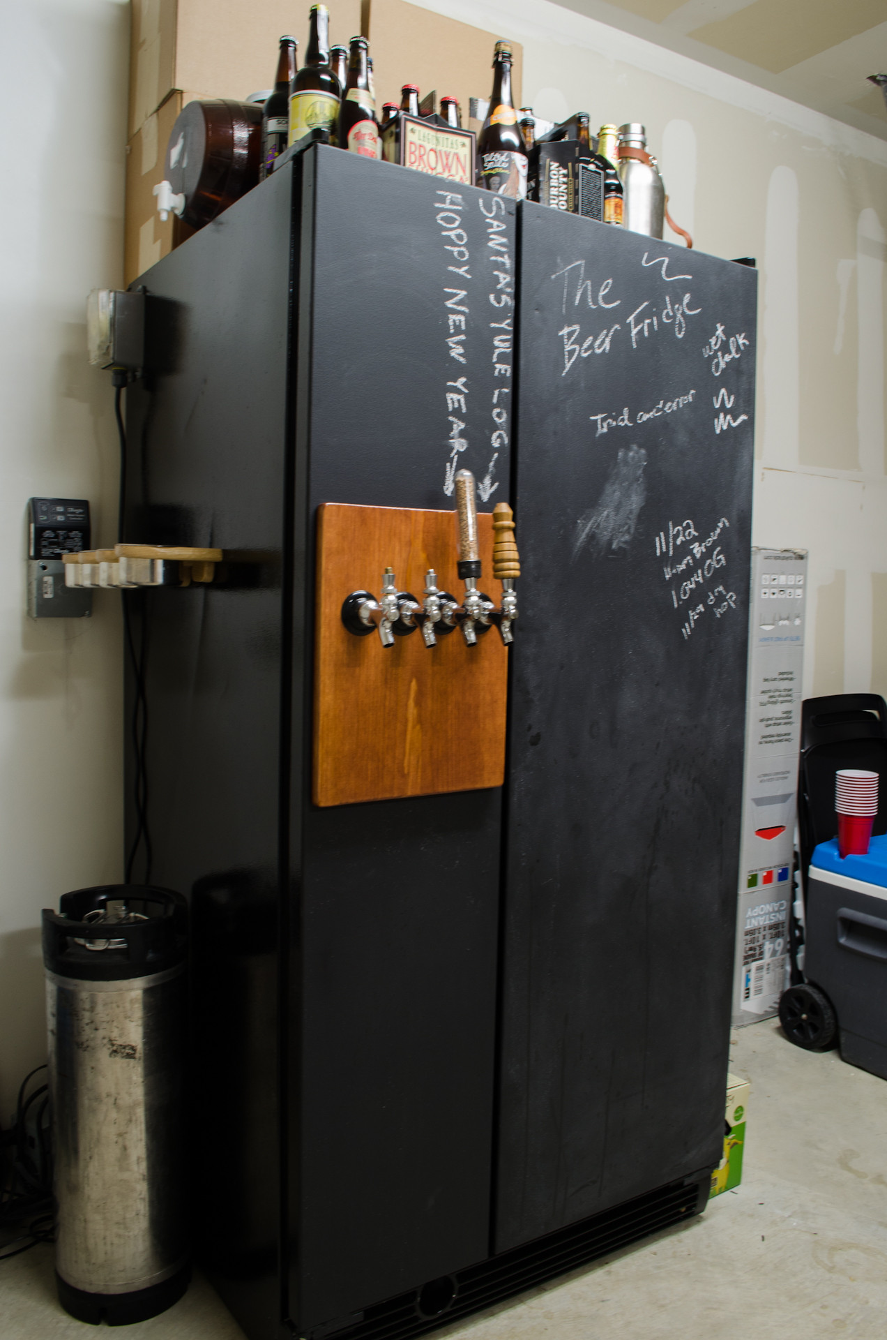
I have decided, as many of you, to convert an old side by side into a keggerator/fermentation chamber. I am starting with an Amana SSD25TW side-by-side refrigerator (picture below). The project is going to include two temperature controllers to keep each side at variable temperatures.
A major problem, though, is that I'm no electrician and this SOB has got one of the most complicated wiring diagrams I've ever seen (see below).
I'm going to use two Inkbird ITC 1000s. Now, I'm thinking, in order to wire this completely correct, I need to replace the current temperature control module (shown in red) with one of the ITCs. That will control the compressor and the temp for the freezer side. If I'm reading this diagram correctly, I'll just need to splice red in to both the power supply and the output power hubs. Then, instead of power outbound to another part of the system, just send the yellow wire coming off of the existing temperature controller. It seems like it heads to two places: the defrost control board's K port (no clue what that means), and the evap fan, presumably to start pumping that cold air all up and down the freezer through the false back wall when the temperature rises over the threshold. Someone please correct me if I'm wrong so that I'm not aimlessly wiring and unwiring things.
The other ITC would be controlling two fans in the center wall to circulate cold air. I've heard the best thing to do is take the neutral line and splice that in to the return line of the evap fan before the defrost system so those fans aren't circulating air when it's on, I'm just not sure where to splice, where I have it labeled (orange lines) or on the other brown line at the 6 o'clock position. Trial and error, again, until someone stops me.
Stay tuned for the rest of the build-out and feel free to offer those good nuggets of wisdom, all you builders out there. I could always use the help.

")


