• Please visit and share your knowledge at our sister communities:
  • If you have not, please join our official Homebrewing Facebook Group!

    Homebrewing Facebook Group

Selector switch that automatically turns off when power's cut?

Homebrew Talk

Help Support Homebrew Talk:

This site may earn a commission from merchant affiliate links, including eBay, Amazon, and others.

kal

Well-Known Member
Joined
Nov 21, 2006
Messages
2,726
Reaction score
543
Location
Ottawa, Canada
I don't know if this sort of switch exists, it may be just me not using the right terminology when searching.

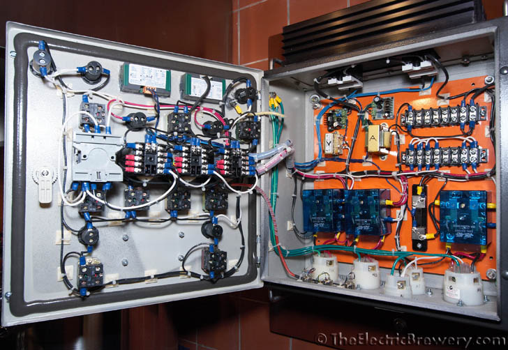
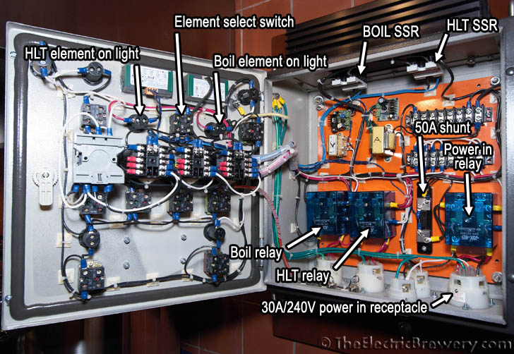
I have a 3-way maintained ELEMENT SELECT switch on my control panel today like this:

IMG_6803.jpg


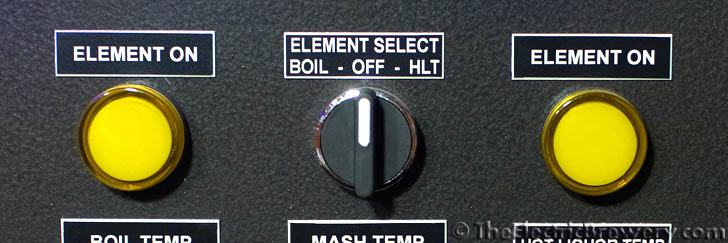
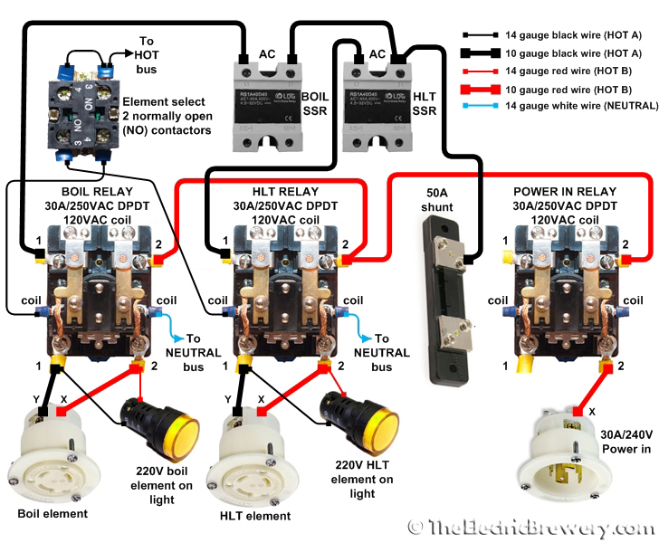
It's used to select which of the two elements (BOIL or HLT) receives power. In the center position both elements are off. This ensures that only one element may be on at once (a design choice I made).

I'm looking for a 3 position maintained switch that springs back to center OFF position if power is cut.

In other words, the two outside maintained positions are somehow maintained but if power to the panel is cut, the switch instead behaves like a spring return switch and springs back to the center OFF position. I imagine to do this, when the switch is turned to either ON position it would have to energize some sort of holding (electromagnet?) circuit that holds the switch in the on position.

Why do I want this?

Today whenever I first turn on the panel power, I have to always *first* make sure that this switch is in the off position. While this is fine for my use, from an ergonomic/process standpoint that's not quite right: When power's cut to the panel, this switch should always reset itself to off for safety reasons. Some sort of interlock is required to make sure someone doesn't trip up. This would stop having an element turn on when then panel is first turned on. (Especially useful for someone who doesn't use ULWD elements which will pop if not turned on while in water).

Anyone heard of something like this?

Kal
 
Kal,
I haven't seen what you're looking for, if it does exist it is pretty specialized which would mean a big price tag if you could find it.

What I would do is put in a 3 position return to center switch. To select an element you turn the switch in that direction and a contact on the switch sets a latch for that contact. It also will open another contact to break the latch circuit for the other element. After you let go of the switch it will return to the center position. You can use a panel light to indicate which element is currently selected. The only problem is you would have to add a second push button to break both latches to turn the element off (break both lathes) during a brew session.

Alternatively, you could add a momentary button to enable the elements. You hit the Enable button and it sets a latch allowing control power to the selector switch. (You can use the same maintained selector switch as is) Once you remove power from the control panel the latch will drop out so the next time it powers up the elements will be disabled until the enable button is pressed. You may want to add a disable button so you can manually drop out the enable latch without having to cycle power to the panel. It's not necessary considering you're not taking any functionality away from the current design.
Personally I like the second option best.

I can provide a drawing if this interests you. If you have a schematic of it's current configuration that would be helpful too.
 
Kal

I don't think you can do it with a maintained switch but....

Using a three position momentary switch, you could add a DPDT relay behind the switch for each position. The control voltage from your key switch then feeds power to the momentary switch and when you toggle in either direction the voltage fires the relay and latches it on the second contact.

To turn either element off, you could change the yellow indicator lights on the panel to indicator switches that have a NC contact block. Then when you press the button it interrupts the control voltage going to the relay latch and opens the contact.

Electrically each element would look something like this:

Key switch>>>>NO momentary switch>>>>NO relay contact>>>>element PID
Key switch>>>>NC indicator switch>>>>NO relay contact>>>>relay coil
 
Yeah, you just need a DPDT 120V octal relay and a momentary PB.

Wire one side of the momentary to 120V, then the output to the relay coil, then Neutral on the other side of the coil.
Next run 120V to one side of a NO contact, then the other side of the NO contact to 120V side of the relays own coil.

Last wire the second NO contact on the relay to break the connection between the selector switch and 'hot bus'.
 
I like the enable button idea. Or is it possible to have the panel not power up if the selector switch isn't in the OFF position?

Kind of like you can't turn on your car if it is in Drive...


I guess you would need a push button to start it or a key that had an Off-On-Ignition selection.
 
Thanks for the sketch CodeRage!

One thing I'm trying to avoid is any changes to the panel in terms of external switches/controls. I'll just leave it the way it is if it comes to that.

JayInJersey has a really intersting idea: Not have the panel power up if the 3-way selector switch isn't in the OFF position.

This is actually really easy to do: I can add two NC contactors to the back of the 3-way switch. They will BOTH be closed when the switch is off. The wire the POWER ON/OFF SWITCH through those two contactors first in series. The POWER ON/OFF SWITCH won't get any power then unless the ELEMENT SELECT switch is OFF.

The catch however is that as soon as you turn the ELEMENT SELECT to either side, you cut power to the panel. ;)

Gotta think about this some more....

Kal
 
CR/Kal

Couldn't you instead add that Enable push button to the key lock (meaning you need to turn key then press button) and wire it so it could only be enabled when both Pumps and the 3 Selector are in the OFF position?

That way you could protect your whole setup when you turn it on in case someone flipped a switch you didn't notice between sessions.


Added bonus to that being on Kal's CP design you could add that button right under the key as there is some free space there.


Just thinking out loud here.
 
I don't blame you a bit for not wanting to change the front of the panel.

So with everyone's suggestions, here's a re-spin using the off position of the selector switch to set the enable latch.

Turn the system on the enable relay wont set until the selector switch has been placed into the off position. After than you can switch till your hearts content.

enable circuit.jpg
 
Now taking that thinking into the realm of the stupid (that would be me :fro:) ...


Would this be a proper bastardization of Kal's power diagram?

power2.jpg


I'm mainly unsure about the first connector on that relay...would that keep it energized even after the button was released and the switches were changed?

Oh and no making fun of my mediocre Visio skills...
 
almost, You need to move the relay to the other side of the switch. Right now the switch wont get powered until the relay is energized, but the relay cant energize until the switch gets power. Other than that, when you make the switch and all the other contacts at the same time, the enable relay will energize.

Yes, a relay will keep itself energized if you power the coil through a set of it's own NO contacts.
 
Ok I see what you mean...had it right on my scribble (you couldn't pay me to show that...) but when I bastardized Kal's I messed it up.

This should be right then?

power3.jpg


And if that is the case...what kind of relay should I be looking for?
Will another of the ones on there work? Cause I can get a deal on another one :D
 
Not sure what kind of relay you are talking about but if is at least DPST or DPDT and rated for enough current to drive the power in relay it should be good.
 
Sorry I was talking about the pictured Power In Relay.

It is a "30A DPDT GENERAL P. POWER RELAY 120v AC COIL" at least according to the eBay auction.

I'm now thinking it might be TOO powerful for the connection. (Is that even possible?)
 
Using the relay ideas, just swap out the "HLT-Off-BK" switch for a non-maintained (momentary) "HLT-BK" switch. Center is off anyway... Your label is even correct that way!

It'll behave like a push button in the same footprint.

Are you looking for the connection to reset if your main power fails? If that's the case, you can swap out your E-Stop for a magnetic contactor - Like on shop class table saws. "On till the power fails, then off" As opposed to "Last state" on power fail.

They should be pretty cheap on eBay.
 
Woohoo! I like it. That's pretty smart - using the output of one of the relay switches to turn back and around and keep the coil energized no matter what happens with the 4 switches.

Any small current DPST or DPDT relay with 120V AC coil should work. The 120V AC coil on the POWER IN relay (or any relay for that matter) is most certainly way less than 1A. The ones I use don't mention what the coil power consumption is.

The funny thing is, I already have the 4 NC contact blocks for the switches. All that's needed is the DPST or DPDT relay with 120V AC coil, ~1A contact rating (or better).

Kal
 
Update: I just measured the current through the POWER IN 120V AC relay coil: Only 36mA. So the POWER IN relay coil only consumes 4.3 watts (0.0036 x 120).

So as I suspected, just about any DPST relay with a 120V AC coil will do as long as the contacts can handle 120V AC as the current through the contacts is so low that it's not a factor.

Kal
 
JayInJersey, blasphemy! No such thing as too much power. :) for something like that I prefer octal based 'ice cube' relays but thats just preference.

Sweet sounds, the 'magnetic switch' on a table saw (I know that is the term they use) internal mechanism is identical to a standard stop start circuit, 1 relay, 2 momentary contacts. The E-Stop is actually an adaptation of that same circuit with a push on/pull off E-stop button.


Kal, yeah when Jay mentioned the Off position of the switch theres no reason why you couldn't qualify the latch with that. Since you wouldn't be adding any more holes to the panel I knew you would love it. You only need 2 NC contacts though not 4. One one each side of the switch wired in series.

Wish I could take credit for the latching relay but that is an incredibly common and useful circuit in controls. :)
 
I guess you wouldn't even need the "Engage" button on my diagram just the relay.

Now I don't have to redesign my panel for the extra button and can just steal, er...emulate Kal's :tank:
 
In case anyone's curious as to what an "octal base ice cube" relay is (I had to look it up), it's like this:

general-purpose-relays-1.jpg


The octal base has to do with the pin layout at the bottom. Ice cube has to do with the clear case. Cool!

CR: I figured this sort of circuitry was fairly common... I thank you for the help anyway! I don't have a relay that fits this purpose in my usual bag of tricks so I'll have to order one with a socket. The trick will be finding a place to install it. My back plane's pretty much full:

IMG_6681.jpg


Is there a "correct" way to install a relay socket on the inside side of the enclosure without having to drill screw holes? not sure I'd want to do that anyway as it would get in the way of other things.

I think the best option is to use the space at the bottom middle of the door where the 4 screws are:

IMG_6710_newrelay.jpg


I could make a small back plate to fit on those 4 screws/nuts which would make it easy to install to socket as it would offset it from the door and the holes are already there. Given that the relay's all what I consider low power and will use 14 ga wiring, nothing wrong with having a relay on the door (IMHO). The switches it connects to are all on the door anyway.

I'm off to ebay...

Kal
 
I guess you wouldn't even need the "Engage" button on my diagram just the relay.

Now I don't have to redesign my panel for the extra button and can just steal, er...emulate Kal's :tank:
The "Energize" button? No. I'm just going to go in series through 4 NC contact blocks on the pump switches (1 each) and two on the ELEMENT SELECT switch. I already have those NC contact blocks too which is perfect. Just need a relay and a socket, and about another 5-10 feet of black 10ga wire and little bit of white.

I never thought of doing this with the pumps too but it makes perfect sense.

I love it! It'll be written up as a optional addendum on my site I think. It would be a complete pain to redraw/rewrite the pictures.

Kal
 
Kal, not really, as long as it's secure you're good. Most bases come with provisions to mount on a piece of DIN rail or to be screwed directly to the inner panel.

If the heat sink doesnt get terribly hot it looks like you may have some room up there by your SSRs.
Edit: ah now the 4 blocks makes sense :)

4 blocks? Sorry, I don't follow.

The heat sink barely gets warm. The bigger issue is how to fasten it. It should be nut/bolt fastened in the two spots on the relay socket. I think it makes sense to stick it on the door. Lotsa room at the bottom.

The 8 pin 2 pole relay with 120V AC coil and socket has been ordered. I'll probably be a couple of weeks before it arrives. Once installed I'll do a write-up on it.

Kal
 
Yeah, thats what those two holes are for. Normally the back plate is drilled and tapped and the screws go through that way.

yeah, I said you only needed 2 but now you are running the pump's off switches in series as well. Explains why you needed 4 nc blocks.
 
You guys seem to have it covered (I didn't peruse each post) but I thought I'd mention a Saf-start. It only kicks in (or 'out' as the case may be) if you lose power while 'running', otherwise you never know it's there. And they're not particularly cheap. It's meant more for motors/equipment you don't want to restart if the power goes out then comes back on. Doesn't really look like what you want/need, only mentioned it because of the 'like you can't start a car in Drive' comment.
 
Last edited by a moderator:
I like to keep it fresh. ;)

The good news is that this add-on with indeed be just that: A simple (optional) add-on.

Kal
 

Latest posts

Back
Top