• Please visit and share your knowledge at our sister communities:
  • If you have not, please join our official Homebrewing Facebook Group!

    Homebrewing Facebook Group

Rims control box

Homebrew Talk

Help Support Homebrew Talk:

This site may earn a commission from merchant affiliate links, including eBay, Amazon, and others.
I was thinking power comes in through the contacts and splits into separate legs in the box. Basically everything in the box is powered by 120v except the heating element. I was trying to figure out if I can use 120v on the PID and low voltage/amperage side of the SSR and 240v on the high side?

Power comes in split as two 120V legs. The contactor just switches both legs, so that when the contactor coil is not energized, not current or voltage is on the load side of the contactor. Nothing splits after the contactor. You can use one of the 120V legs and neutral to power any 120V device. As said previously, if you use a 4 wire feed derived from a 3 wire feed (via a spa panel) you should balance the current draw of the 120V devices between the two 120V hot legs. If you don't understand how to do this, you really should get some local help with electrical expertise.

Do you have a circuit drawing of the design you are using?

Brew on :mug:
 
I wanted to get everything set up In the box before I draw a diagram. I understand what your saying, the load would be minimal on the 120v (just a pump). I guess a more specific question would be if I pull power to the pid should I just use one leg? Or because I'm switching 240v should I wire the pid for 240? It can run on either. I just wanted to know if it would be okay to run it with the 120v.
 
I wanted to get everything set up In the box before I draw a diagram. I understand what your saying, the load would be minimal on the 120v (just a pump). I guess a more specific question would be if I pull power to the pid should I just use one leg? Or because I'm switching 240v should I wire the pid for 240? It can run on either. I just wanted to know if it would be okay to run it with the 120v.
Doesn't matter what voltage you run the PID on. The PID has an internal voltage regulator that takes what you give it and outputs the internal voltage(s) the PID needs to operate. The control outputs of the PID to the SSR are low voltage DC, and the output voltage is independent of the supply voltage. The control inputs of the SSR are optically isolated from the power input/output, so it doesn't matter what voltage the SSR is switching.

Brew on :mug:
 
A little has changed given my useable space because the door lock and the water proof seal on the door.


I am looking at that same enclosure for a similar build, could you give me an idea on the height & width of the usable space?

Looking great so far!
 
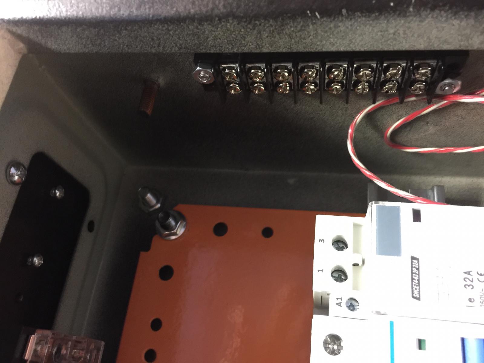
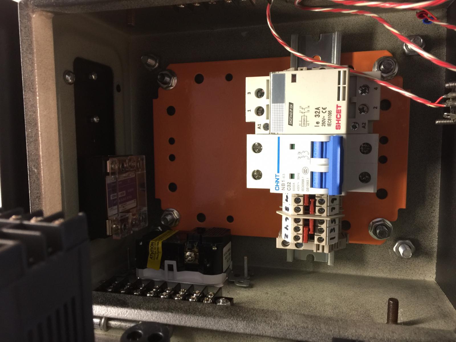
Thanks man. Useable space on the front cover is about 6"x8" it's about 4 3/4" deep. It's kind of a tight fit but there's enough space for everything to be run cleanly.
 
Hey Doug, I've heard through the grape vine your the man when it comes to wire diagrams. Any chance you could help me out? I have another preliminary sketch but I need to change it again.
 
Hey Doug, I've heard through the grape vine your the man when it comes to wire diagrams. Any chance you could help me out? I have another preliminary sketch but I need to change it again.

Yes, I can help. Need details on just what you want.

Brew on :mug:
 
Okay so attached is my diagram but I'll explain what I have and see if my dreams are compatible. So I wanted power going in through a contactor and that being switched by my E-stop and a power switch. I realized that is going to be two switches controlling the same thing. Next I wanted 3-4 LED's. I wasn't sure where to put them on the diagram and what voltage I needed. For main power can I just LED one leg at 120v? And for the heating element do I LED the control side of the relay or the output side with a 240v led. Here's is what I have as a diagram. (In my inventory I have 3 120v leds and one 240v. I have 3 switches 10A and an 10A E-stop) I wanted to switch the control side of the relay to kill the element at any time and possibly led this as well. LED and switch main power and pump.

Looking at my diagram I realized I left a wire or too out. Or three or four.

IMG_0095.jpg
 
Last edited:
Okay so attached is my diagram but I'll explain what I have and see if my dreams are compatible. So I wanted power going in through a contactor and that being switched by my E-stop and a power switch. I realized that is going to be two switches controlling the same thing. Next I wanted 3-4 LED's. I wasn't sure where to put them on the diagram and what voltage I needed. For main power can I just LED one leg at 120v? And for the heating element do I LED the control side of the relay or the output side with a 240v led. Here's is what I have as a diagram. (In my inventory I have 3 120v leds and one 240v. I have 3 switches 10A and an 10A E-stop) I wanted to switch the control side of the relay to kill the element at any time and possibly led this as well. LED and switch main power and pump.

Looking at my diagram I realized I left a wire or too out. Or three or four.

Have you decided which brand of PID you want to use? I always recommend the Auber EZBoil, as it isn't as difficult to tune as a regular PID. It also works great for boil control. What about element power, and connection to element?

Brew on :mug:
 
And for the heating element do I LED the control side of the relay or the output side with a 240v led.

Remember that visual indicators are tools to help convey information about your system when its working properly and also when there is a malfunction.

You can put LED indicators on either the control side or load side of a relay, but I suggest putting them across the load you are switching with the relay.

That way, if an SSR or relay fails in the closed state, the LED will let you know that has happened, (hopefully before something boils over or an element dry fires).

If the LED is just monitoring the control side of a relay, you might not realize the SSR has failed
 
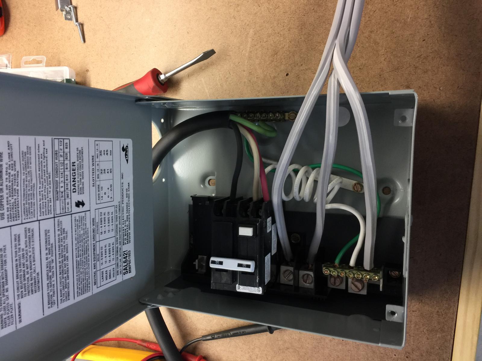
I went with the syl-2352. I bought it before I read your recommendation. Element I wanted to run 240v but a lower wattage element. I have a 25A SSR and I didn't think I'd need that much power in the tube. The connection I wanted to use is from brewers hardware in Huntington Beach CA, for the element, it's a TC fitting. I think I was going to go with 3 wire into 4 wire via spa panel otherwise I'd have to run a nuetral wire from the breaker in my wall to the outlet. On the bottom of the box I was going to put a standard 120v power outlet (double) unless you advise against using both in that set up. Also a plug for the element and a main power entry point.

Thanks for the information on the LED's
 
Last edited:
Remember that visual indicators are tools to help convey information about your system when its working properly and also when there is a malfunction.

You can put LED indicators on either the control side or load side of a relay, but I suggest putting them across the load you are switching with the relay.

That way, if an SSR or relay fails in the closed state, the LED will let you know that has happened, (hopefully before something boils over or an element dry fires).

If the LED is just monitoring the control side of a relay, you might not realize the SSR has failed

Exactly.

Brew on :mug:
 
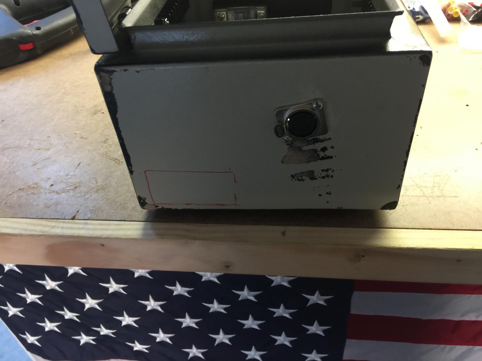
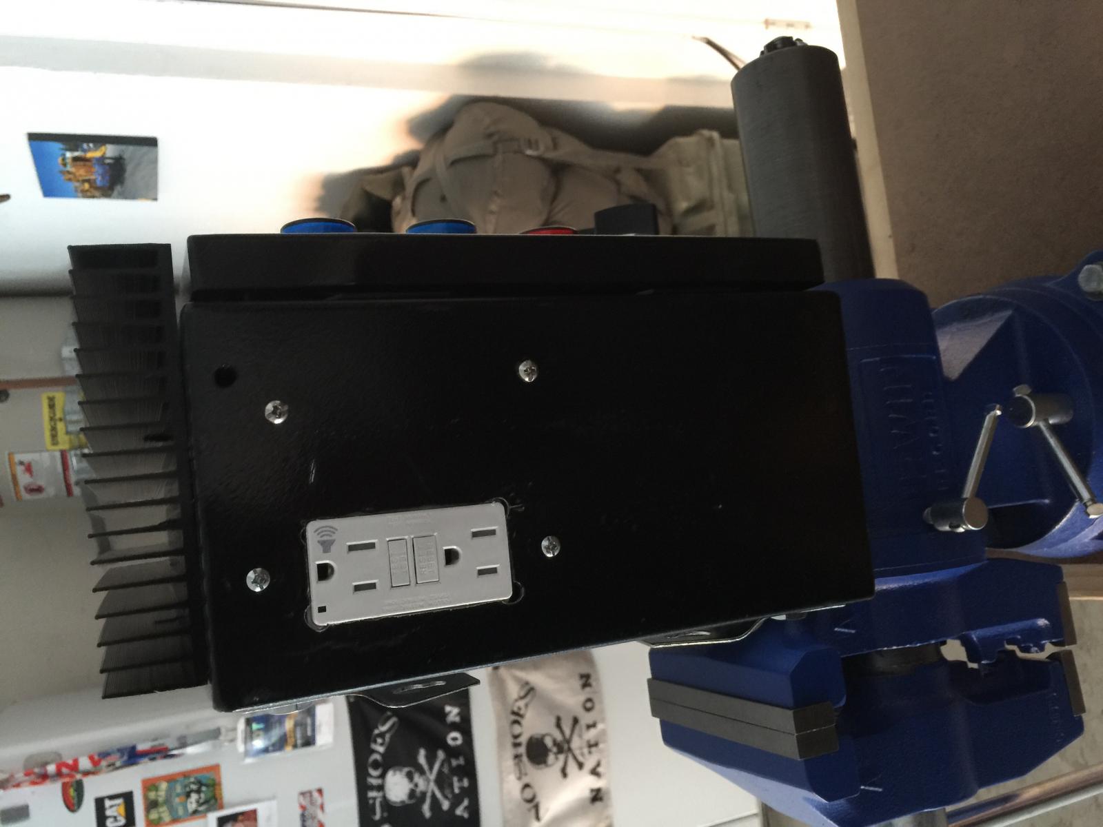
Side profile. I still need to add another layer a paint drill the holes for power supply coming in and for the heating element plug.

image.jpg
 
This should be close to what you are looking for. Element power enable switch/contactor is interlocked by the pump switch, so that element can't be powered unless the pump switch is on. (It's up to you to remember to plug in the pump. :D)

SYL-2352 1-Pump RIMS 240V.jpg

Brew on :mug:
 
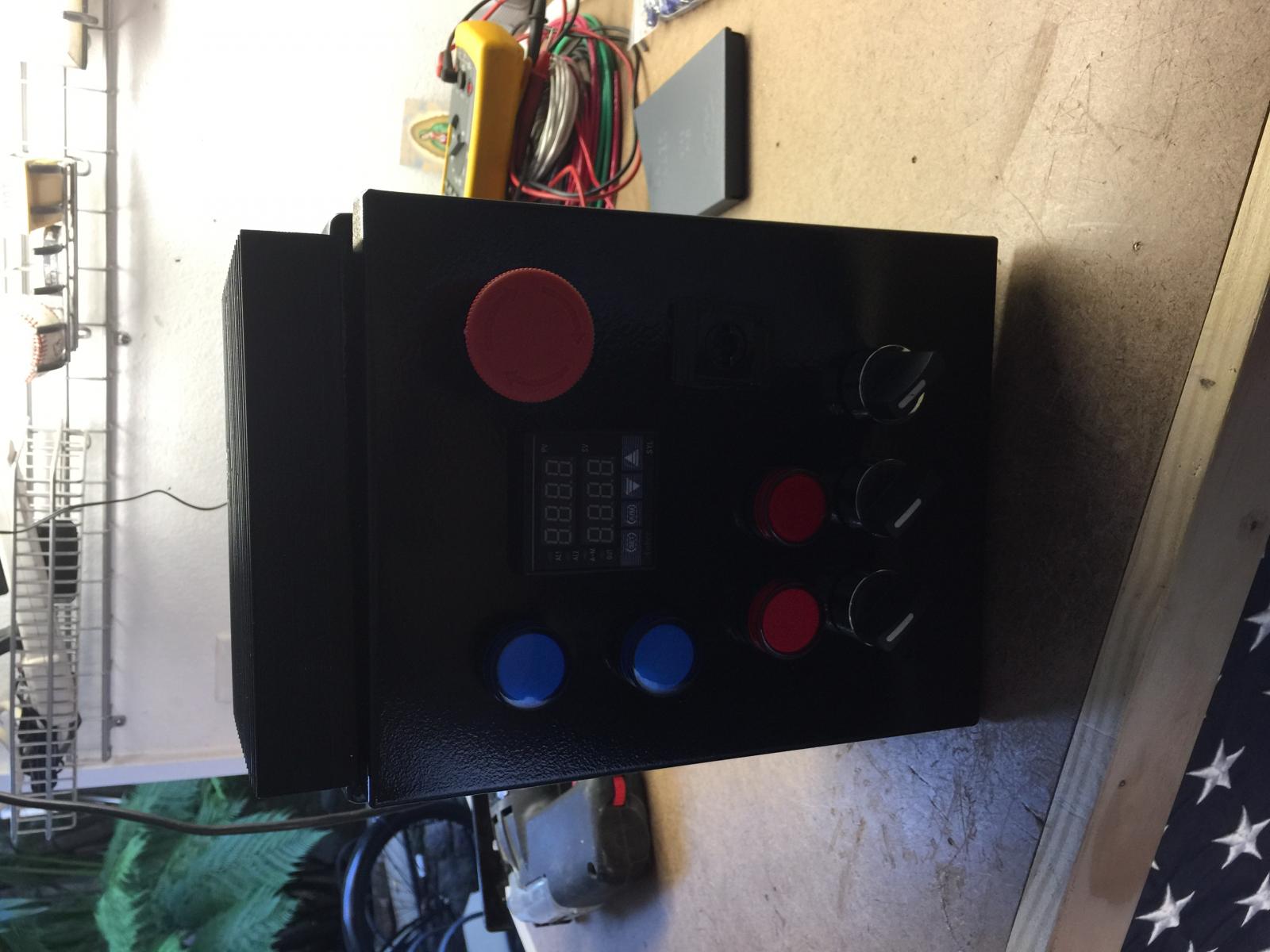
I know this is getting old but just wanted to show the finished (some what) product. So far all testing is okay and both my GFCI breakers are working. It did trip my spa panel once but nothing was connected to it. Anyways here's the pictures

IMG_0131.jpg


IMG_0132.jpg
 
I owe it all to you Doug. Thanks for all your help. I couldn't have done it without you're explanations.

As well as everyone else that on this thread that chipped in. Thank you all.
 
Back
Top