• Please visit and share your knowledge at our sister communities:
  • If you have not, please join our official Homebrewing Facebook Group!

    Homebrewing Facebook Group

Question about 240v lights for control panel

Homebrew Talk

Help Support Homebrew Talk:

This site may earn a commission from merchant affiliate links, including eBay, Amazon, and others.

micahwitham

Well-Known Member
Joined
Jun 3, 2011
Messages
50
Reaction score
3
Location
richfield
On accident I ordered my yellow element selector lights first and then Amazon and the person behind the curtain watching all of my buying habits recommended the blue, green and red lights I need for power, pumps and alarms. Problem is that they are all 240v lights instead of the 120v that require a hot from the selector switch and a neutral run to the neutral bus bar.

Here's the question: Can I run both legs of hot L1 & L2 into the switches and out of the switches to all the lights just like I would run L1 into the switch to the light if I had 120v lights? I guess it's a question for the selector switch and it's capacity.

tried to diagram below...
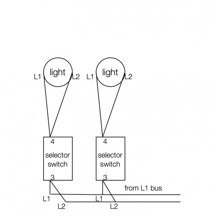
diagram.jpg
 
You have to back up and understand how 240v works. I think you ought to post a diagram of how you were planning to wire your whole panel because I'm not confident the rest will be correct.
 
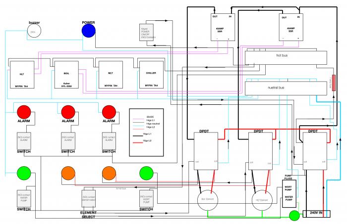
So here's my diagram so far...
I've got some feedback from a couple of site members that the 240v lights will work with 120v but just may be a bit dimmer. So right now I have it drawn up to have all the lights except for the element selector switch lights to be 120v with a L1 and Neutral.

Pick it apart and tell me what you think. I'm not an electrician as my diagram shows but I'm doing my best to learn all that I can from this site and others to make this thing come alive. Big thanks to TheElectricBrewery and all of Kal's diagrams...SUPER HELPFUL as many already know.

Any other places you would put fuses to protect things?
Also, I don't have the buzzer wired up yet because I haven't figured that out without using the Omega Timer on Kal's design and I have the MyPIN's and the Auber so it's different numbering but if anyone has any help on that I would appreciate it!

wiring diagram.jpg


View attachment wiring diagram.pdf
 
There is nothing stopping you from connecting 120v L2 to one side of your indicators instead of neutral and the other side of the indicator to 120v L1 controlled by the switch.

On most designs you only need L2 to go from the power intput connector through the contactor and SSR directly to the heating element.
 
Back
Top