Prepping 30A Single Vessel, Single Element PID BIAB (240V)

Homebrew Talk - Beer, Wine, Mead, & Cider Brewing Discussion Forum

Help Support Homebrew Talk - Beer, Wine, Mead, & Cider Brewing Discussion Forum:

This site may earn a commission from merchant affiliate links, including eBay, Amazon, and others.

Lumpyyyyy

Well-Known Member
Joined
Jan 12, 2012
Messages
245
Reaction score
6
Location
New Hampshire
I am working on putting together a build that will allow me to run a BIAB off a single element. The requirements that I have given myself are as follows:

1. 240V (Access to current 240V supply through laundry outlet and panel in basement when basement room refinished)
2. Single element
3. All items purchased should be expandable to 3 vessel setup (with exception of enclosure)
4. Use PID controller
5. Switches to turn on and off elements/pumps rather than push button illuminated LEDs
6. RTD Elements
7. Single Pump

In doing my work, I came across the following kit on eBrew Supply:

http://www.ebrewsupply.com/shop/ebrew-kits/ebrew-pid-kits/1-pid-30a-biab-kit.html

It contains (seemingly) the majority of the items I needed to put together my system. I have the following items to purchase extra:

iRflaYe.jpg


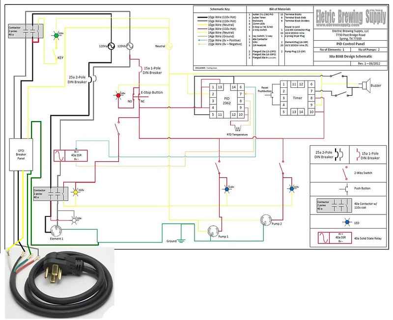
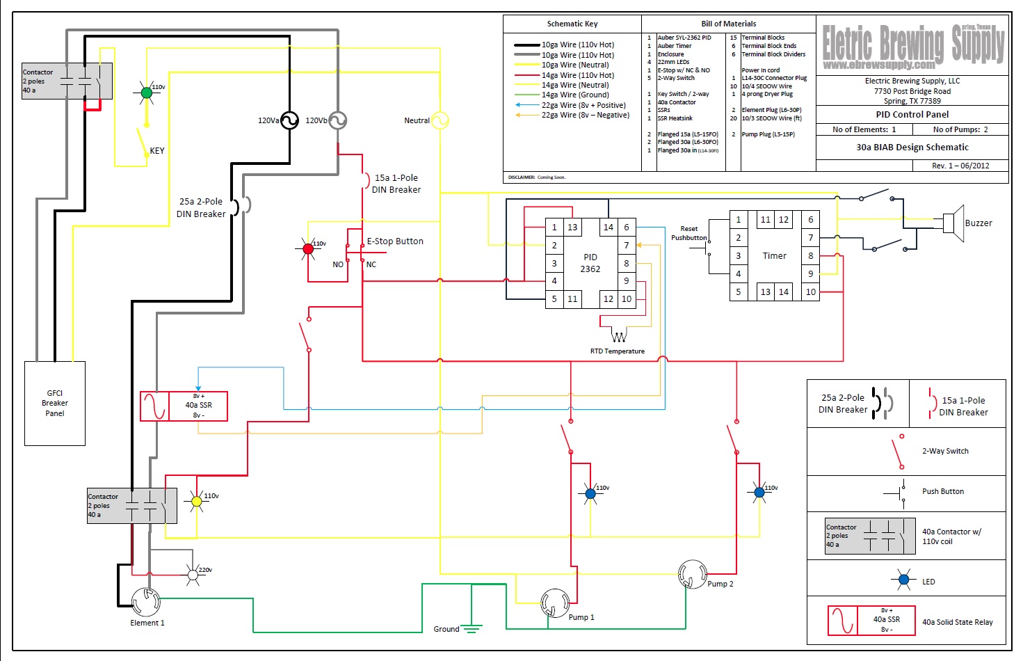
And here is the wiring schematic I am going to follow:

GWuxho1.jpg


My questions are as follows:

The outlet near my dryer is 4 pins while the wiring diagram only shows 3 in. Can someone explain this to me?

Does anyone see anything I missed out on in my BOM? Other than kettle which I will already have.

If anyone has any constructive criticism, I'm all for it. Please let me know. Minus the pump, I'm around 600 which seems pretty reasonable for this type of setup.
 
The 4th wire is the ground. The schematic isn't showing it but the receptacles and GFCI breaker panel would be tied together...
 
The 4th wire is the ground. The schematic isn't showing it but the receptacles and GFCI breaker panel would be tied together...


I'm not sure I follow exactly. What do you mean the receptacles and GFCI would be tied together?


Sent from my iPhone using Home Brew
 
I'm not sure I follow exactly. What do you mean the receptacles and GFCI would be tied together?


Sent from my iPhone using Home Brew

Your source in the schematic is only showing a Hot,Hot,Neutral. You'll actually have Hot,Hot,Neutral & Ground coming from you source (4 prong dryer plug) to your GFCI and from there on to your control panel. The 3 receptacles in the schematic that the control box is controlling are shown bonded to ground (ie the ground the symbol and green wire). The ground would tie all three back to your home's ground rod via the ground wire. It's not shown in the schematic but the ground connects all the way through.
 
Your source in the schematic is only showing a Hot,Hot,Neutral. You'll actually have Hot,Hot,Neutral & Ground coming from you source (4 prong dryer plug) to your GFCI and from there on to your control panel. The 3 receptacles in the schematic that the control box is controlling are shown bonded to ground (ie the ground the symbol and green wire). The ground would tie all three back to your home's ground rod via the ground wire. It's not shown in the schematic but the ground connects all the way through.


So in addition there would be a wire from the ground rod back to the ground in?


Sent from my iPhone using Home Brew
 
this is the one I use, built it years ago and don't remember the diagram but the dial is an arduino pulse that I use for the boil, the bottom right selector switches between the pid and arduino, the selector above the dial turns the power on to the ssr, the top selector runs the pump, the light flashes when the element is on. the very bottom right corner has the plug for the RTD PT100 prob

panel.jpg
 
this is the one I use, built it years ago and don't remember the diagram but the dial is an arduino pulse that I use for the boil, the bottom right selector switches between the pid and arduino, the selector above the dial turns the power on to the ssr, the top selector runs the pump, the light flashes when the element is on. the very bottom right corner has the plug for the RTD PT100 prob

Is the dial used for controlling the output during boil? I believe the PID has manual option to dial down when you want to not run at 100% or PID controlled.


Does that make more sense?

Yes, that makes entirely more sense. That's what I was thinking but wasn't quite sure.
 
Probably not the advice you were looking for but I think you have made a mistake on your estimate - you have only added 10% extra (not 30%) for unexpected costs. Just don't want to see you have and unexpected $200 cost blowout :D
 
Probably not the advice you were looking for but I think you have made a mistake on your estimate - you have only added 10% extra (not 30%) for unexpected costs. Just don't want to see you have and unexpected $200 cost blowout :D


Thanks. I had it at 30 and changed it in the percentage and not title.


Sent from my iPhone using Home Brew
 
Boil over protection would be flipping the switch that operates the element contactor no?

Just curious why you have 25amp breaker in the box. If you use 10 gauge wire in the box for the high current stuff, you'll be fine protected by the breaker in your main panel.
 
Boil over protection would be flipping the switch that operates the element contactor no?

Just curious why you have 25amp breaker in the box. If you use 10 gauge wire in the box for the high current stuff, you'll be fine protected by the breaker in your main panel.


I didn't design the schematic, it's from ebrewsupply. I honestly couldn't tell you why it's there.

And I suppose I could use that as well. Turning it off and just changing Pid manual parameters.


Sent from my iPhone using Home Brew
 
I haven't done it but just thinking through it is that you could leave the PID in auto mode with a setpoint of one degree below boiling and have it trip the alarm when it gets there. That's your cue to hit manual and dial in the boil rate (and watch for the first hot break).
 
I haven't done it but just thinking through it is that you could leave the PID in auto mode with a setpoint of one degree below boiling and have it trip the alarm when it gets there. That's your cue to hit manual and dial in the boil rate (and watch for the first hot break).

That's what Kal has documented many times. :)
 
I haven't done it but just thinking through it is that you could leave the PID in auto mode with a setpoint of one degree below boiling and have it trip the alarm when it gets there. That's your cue to hit manual and dial in the boil rate (and watch for the first hot break).

This is what I do.
I think everyone gets a bit carried away with impractical bling..... I'm just as guilty lately... just another toy to impress and sell... If you think about it having three pids instead of just using switches or unplugging and switching elements/element plugs would be more practical for the way many actually brew but all the cool bling makes the system more entertaining to build and operate... I keep adding to mine just for the fun of it.
 
Lumpyyyyy


this is the same design and code I used, I think mine is slightly different but close

http://www.tantonweather.com/arduino-pwm-schematic-and-details/

before I had this I just switched the ssr off but that would stop the boil immediately and take a while to restart, I figured out that its very easy to boil with the dial, turn up and down very easy, I just use the pid while boiling for the temp display and it seems to have made the brew day easier and thats all that matters lol

I know this is an old thread, but the arduino manual mode is something I really want to incorporate into my build. And the link is dead :(. Is there another schematic or something you could possibly link?
 
I know this is an old thread, but the arduino manual mode is something I really want to incorporate into my build. And the link is dead :(. Is there another schematic or something you could possibly link?

I did a search around to see if I could find anything on the original URL (Web archive, etc) and found the following site:

http://tylertanton.com/homebrewing/

Scroll down a bit on that site, I have a feeling it might be the same content.
 
Back
Top