Planning the Brichaus E-brewery build

Homebrew Talk - Beer, Wine, Mead, & Cider Brewing Discussion Forum

Help Support Homebrew Talk - Beer, Wine, Mead, & Cider Brewing Discussion Forum:

This site may earn a commission from merchant affiliate links, including eBay, Amazon, and others.

Brickout

Well-Known Member
Joined
Feb 6, 2010
Messages
262
Reaction score
35
Location
Lockport, IL
First off, thanks to everyone on this forum for all the information. I've been reading for countless hours and the information is priceless.

So I'm planning a simple e-kettle to start with. It's really not much different than a eBIAB setup. Power will be supplied by a GFI spa panel, typical power cords. The kettle will also be the typical setup, element, weatherproof box, rtd temp. sensor, etc.

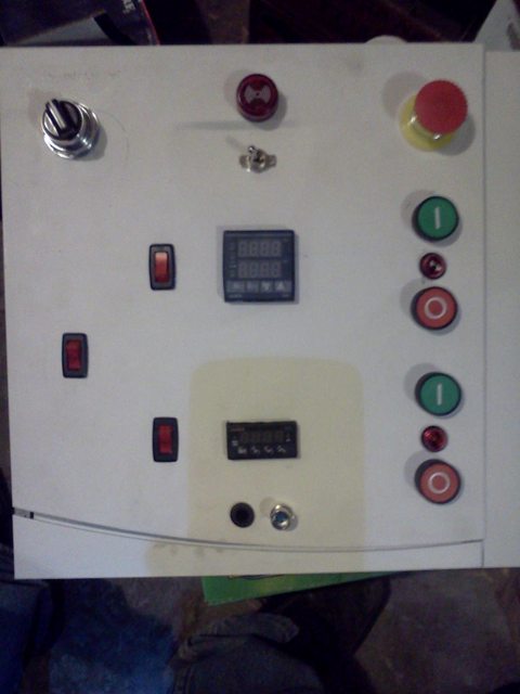
The real meat of the project is in the control box. The idea I have is to build more of an antiquated looking control panel. Part art, part function.

Here's the list of parts I'm thinking of using. Let me know if see anything that won't work.

Switches

Indicator Lights
  • Main Power - Jewel pilot light, 120v, green - eBay
  • Element - Jewel pilot light, 120v, yellow - eBay
  • Pump - Jewel pilot light, 120v, blue - eBay
  • Alarm - Jewel pilot light, 120v, red - eBay

Components

Connections
  • Power in - NEMA L1430 turn-lock Male Flanged Receptacle
  • Element out - NEMA L6-30 turn-lock Female Flanged Receptacle
  • Pump out - NEMA L5-15 turn-lock Female Flanged Receptacle
  • RTD in/out - Panel mount connector for RTD

Misc.
Terminal strips
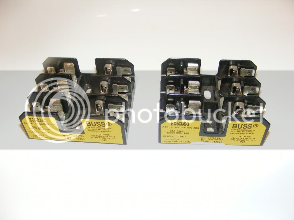
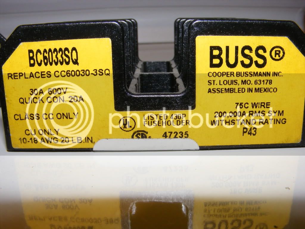
Fuses and fuse holders

For the wiring diagram (I could use a little help here) I'm thinking something along the lines of voltin's setup

wiring-diagram.jpg


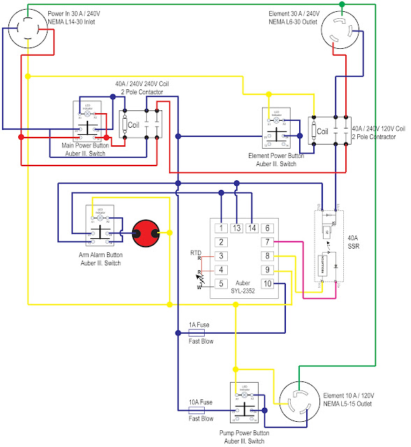
The differences would be the addition of the E-stop, different switches, and indicator lights.

Any advice or help on this project would be greatly appreciated.

-Chris
 
Last edited by a moderator:
I think you need a 240V pilot light for the "element on" indicator. I am not the right guy to bless this, but that one jumped out at me.
 
I think you need a 240V pilot light for the "element on" indicator. I am not the right guy to bless this, but that one jumped out at me.

Yeah, I'm trying to figure out a wiring schematic myself. I was looking at Kal's site here. I'm wondering if that will work with a contactor, or do I need to get a relay?
 
O K, so I made some changes to the plan and the wiring. I was looking through PJ's diagrams and came up with this.

Switch #1 uses Gringer part# 2TPF8 DPDT switch
Switch #2 uses Gringer part# 2VLN5 SPST switch
Switch #3 is still the same keyed switch.

The only part I cannot figure out is how to wire up the alarm. I'd like to be able to flip a switch to activate the alarm circuit and turn on an indicator light that the alarm is on. When the buzzer goes off from the alarm, I'd like to be able to flip the same switch to the "off" position to turn off the buzzer and indicator light.

Brichaus Wiring.jpg
 
So I was giving the alarm circuit some thought last night. I think if I use a DPST switch it could work. One set of the poles activates the indicator light. The other set completes the buzzer circuit.

On another note, I got my control panel off of eBay last night. I got a Hammond EJ10106 for $20 shipped. It's 10"x10"x6", so it should be big enough for my project.

I'm also planning on picking up this Camco element from Home Depot.
 
Sounds like you're off to a good start. Your contactor and SSR choices will work fine.

A 120V pilot light will work fine for the element on, as long as you only care if it lights when the element *should* be receiving power.

You can wire the pilot light off of the hot leg of the switched SSR output, then to neutral. It will run on 120V and you'll be fine. As for the alarm circuit, that's what I was going to suggest when I read your requirements, (and now I wish I'd done the same!).

The other option would be an illuminated switch. The switch itself would light up when on, (regardless as to whether or not the alarm was sounding), and when shut off it would go dark, and the alarm would shut off. Easier to wire, but doesn't fit in with the rest of your pilot lights. A pushbutton illuminated switch like the ones PJ always suggests would work fine. For a cheaper option, I got rocker switches, 120V, 10A, illuminated, from Menards for like $4. Pic of them on my panel here:
oPRGkl.jpg


Full pic here:
xlcMSl.jpg
 
I took another crack at the wiring for the alarm. I think I got it right, tell me what you think.

Brichaus Wiring v2.jpg
 
So I got the SSR ordered today and managed to pick up a keg for my kettle. So things are kinda on their way.

What's everyone's thought on this fuse block from Radio Shack?
 
its only rated to 20A

If you want I have a couple fuse blocks left over that I could probably part with for $5ea.

DSCF3247.jpg


DSCF3248.jpg


I have extras because I bought them in bulk when the cheapest I could find them in town was $20 each
 
Well so far I've received my SSR, the jewel lights are in transit, I have two kegs for keggels, and the 50A GFCI breaker has been ordered.

Parts are starting to add up. But I still have a lot left to order.
 
I'm a bit confused as to why you are using a SPDT switch for the buzzer and an indicator light. With that arrangement they will both be either on or off.
 
If I understand correctly how the PID works, when you activate the alarm, wire #1 & #14 send 120v to what you have wired to them. I'm using DPST switch to; A) Turn on the indicator light to let me know that the alarm buzzer is "live". and B) To be able to quickly turn off the buzzer when the alarm is triggered.

So far I think I have it designed correctly. But I haven received much feedback on the diagram.
 
I'm not terribly familiar with the Auber products, but I am quite familiar with control logic and use it everyday as a mechanical engineer. I don't think that your alarm circuit is going to work that well. Figure 5.2, page 6 of the following shows how the wire the alarm circuits.

http://auberins.com/images/Manual/Manual version 3.4.pdf

I'm afraid that you could have two active alarms (while they will be in-phase) and you won't be able to control them independently.

I would use something more along the lines of the following (which is what I used). This is a DPST switch that would allow either the alarm or the light to be active, but not both. The way you have it shown now will make the light and the alarm active, or "on", at the same time, or off at the same time. That seems redundant to me; I would have either the light or the alarm active, but not both. That's just my 12 ounces of advice so take it for what you paid for it.

eBay - New & used electronics, cars, apparel, collectibles, sporting goods & more at low prices

Terminals 1 and 14 are two separate alarm circuits, both being fed by terminal 13. You would need to put the light inline with #13 to know that the buzzer is "live" and then tie the buzzer to 1 or 14 to have it turn on with the alarm circuit.

Thanks for the input. You've given me a few things to think about.
 
Got more parts ordered today from Amazon.
I ordered:
One PETRA 90-2028 4-Wire Dryer Cord, 10-Foot for $18.95 for power to the control box.
Two PETRA 90-1024 3-Wire Dryer Cord, 6-Foot for $11.83 for the HLT & BK element power.
Two Leviton 800-05207-00K Dryer Receptacle for $6.03 for the control box element outlets.

Here's the best part, the order total was enough to get free shipping. Then if you applied the the Amazon Chase credit card you got a $40 credit. So the total after free shipping and $40 credit came to $14.67 for everything.
 
Last edited by a moderator:
I've picked up a few small parts but not much to show. I've got a plate chiller on order and I'm going to look at a stainless sink tomorrow.

Fund have been a little low.
 
kgalle said:
I can just see all the panicky valve turning.

Yeah, like the ooppps I forgot to close the kettle valve while filling up. It takes 6 minutes of turning to shut it off. That's hilarious .
 
I've made some changes to my wring diagram.

BrichausWiringv3.jpg


My first question; Do I have all the necessary fuses with the correct amp amounts?

Second; For switch #1, the DPDT for the HLT and BK, I was planning on using McMaster model #7343K791. And for the rest of the switches I plan on using McMaster model #7343K711. I these O K to use?
 
P-J, thanks for catching that.

Looking at the spec's on that switch is listed at, "Contact Rating @ 250V (Amps) - 15".
This is O K to use? Not that I'm questioning you. I just want to make sure I'm getting the correct switch.
 
Those switches are fine for our application as the voltage measured to ground from any point is 120V. Both 120V phases are open whenever the switch is off and therefore the voltage across the switch points when off would still not be 240V (Zero in fact). It is more than capable of carring the current needed (25A).

Hope this makes sense & helps.
 
Back
Top