
stever1000
Well-Known Member
- Joined
- Oct 15, 2014
- Messages
- 822
- Reaction score
- 49
I have done quite a bit of wiring before and I am comfortable with diagrams, but I thought if there is someone with experience, it would be nice to confirm!
Yes, it's a storage container. It's temporary because I can't find an inexpensive enclosure in Canada. I am going down to Oregon this September and will stop at HD there
I used this wiring diagram, Single Element BIAB 30A PID from P-J (image doesn't work from his website)
with the exception of the 110V outlet for the pump is swapped for a AC-DC converter. I have no lights on my switches. The E-Stop's resistors are wrapped in electrical tape so cannot be seen.
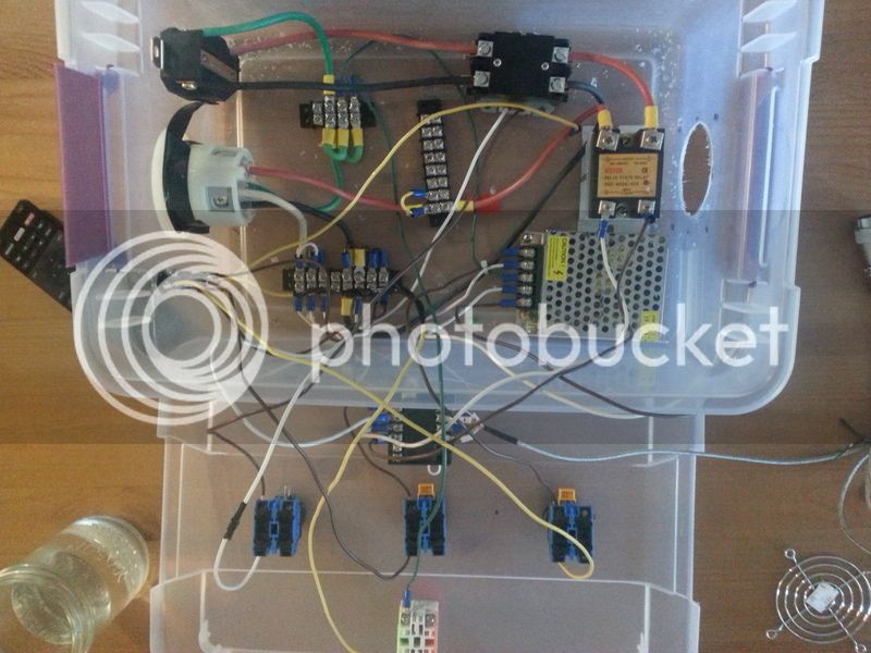
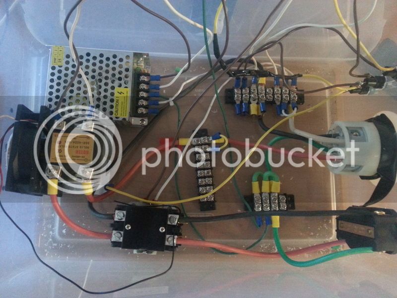
10 gauge and 14-16gauge wire used where needed. 240V 4 wire in from stove/range outlet in kitchen to Spa Panel then to enclosure. Element is 5500W
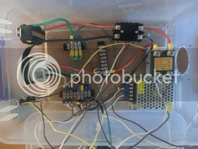
Top left is the element plug, and bottom left is the feed from the spa panel.
The yellow wire going across the enclosure was connected after the photo was taken to L2. Ground is top left terminal block, L2 is right, and Neutral and L1 share the long one on the bottom. Black/brown is L1, Red is L2, green is ground and white is N. The fan is not connected yet and the fuses use brown and yellow to make it confusing. I traced each wire, end to end and confirmed on the diagram. Anyone have any comments? I apologize some of the pictures are upside down.
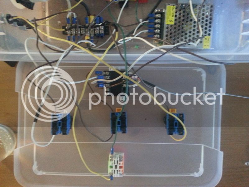
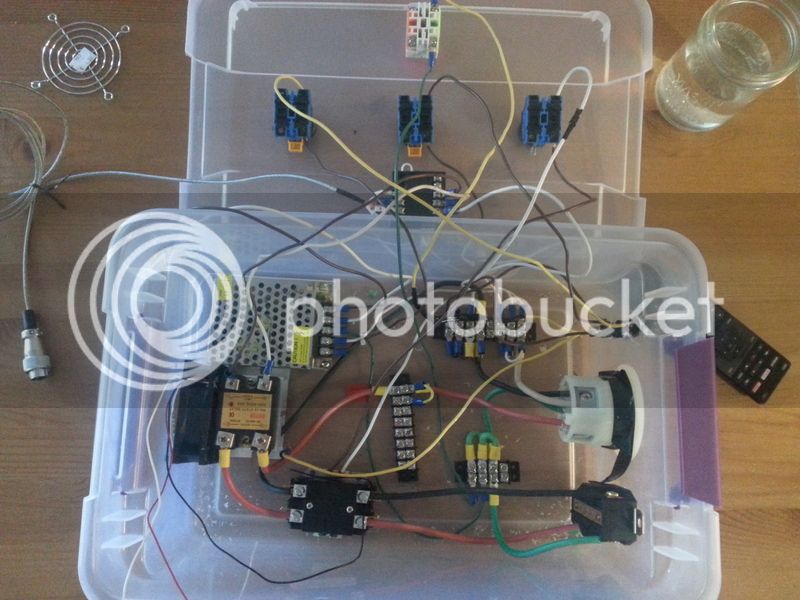
The switches are: Left: contactor, middle: PID, right: AC-DC converter (pump) and bottom is E-Stop:
Yes, it's a storage container. It's temporary because I can't find an inexpensive enclosure in Canada. I am going down to Oregon this September and will stop at HD there
I used this wiring diagram, Single Element BIAB 30A PID from P-J (image doesn't work from his website)
with the exception of the 110V outlet for the pump is swapped for a AC-DC converter. I have no lights on my switches. The E-Stop's resistors are wrapped in electrical tape so cannot be seen.
10 gauge and 14-16gauge wire used where needed. 240V 4 wire in from stove/range outlet in kitchen to Spa Panel then to enclosure. Element is 5500W
Top left is the element plug, and bottom left is the feed from the spa panel.
The yellow wire going across the enclosure was connected after the photo was taken to L2. Ground is top left terminal block, L2 is right, and Neutral and L1 share the long one on the bottom. Black/brown is L1, Red is L2, green is ground and white is N. The fan is not connected yet and the fuses use brown and yellow to make it confusing. I traced each wire, end to end and confirmed on the diagram. Anyone have any comments? I apologize some of the pictures are upside down.
The switches are: Left: contactor, middle: PID, right: AC-DC converter (pump) and bottom is E-Stop:

