• Please visit and share your knowledge at our sister communities:
  • If you have not, please join our official Homebrewing Facebook Group!

    Homebrewing Facebook Group

ON/Auto/Off Pump Switch with safe start?

Homebrew Talk

Help Support Homebrew Talk:

This site may earn a commission from merchant affiliate links, including eBay, Amazon, and others.

givagodamazio

Member
Joined
Apr 20, 2020
Messages
9
Reaction score
1
Hi!
I am creating the wiring diagram of my new eBIAB panel (95% based on existing diagrams from this forum :;) )and it's all going good, except for one part that is burning my head.
The system will have the EZBoil DSPR320 so I want to take profit of it's automatic pump control option.
I was thinking to have my pump switch with 3 positions, On / Auto / Off. I wanted to include the safe start loop designed by Doug293cz, but all switches that I found have to NO blocks and a off position, but no NC block for the safe start.
I could add a NC block but will that work? Won't it be NC for a specific position only, I mean, NC will be close only when On is open.

Any help will count.
Thank you so much!

I will post diagrams here when they are ready.

Cheers!
 
Have you considered using a center-off toggle switch? I use them for exactly that auto/off/on functionality...

Cheers!
Thank you for your input! As I understood from the specifications of SW19 from Auber Inst. the off position has no current as it is not a channel:
https://www.auberins.com/index.php?main_page=product_info&cPath=69_32&products_id=743
What 3-way switch do you use? Does your switch has a NC channel on the OFF position?

Thank you day_trippr!
Cheers!
 
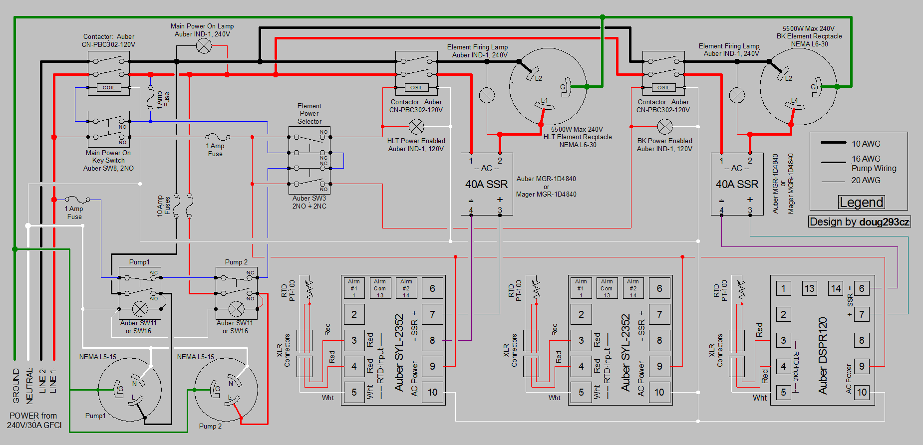
The following schematic shows how to use a three way (on-off-on) switch in the safe start interlock. It requires stacking two NC blocks on the standard NO blocks. The NC blocks only open up when the switch is activated into their position, so one of the NC blocks will be on-on-off and the other will be off-on-on.

I wouldn't wire the safe start exactly as shown in this schematic anymore. It works, but has some subtle quirks that can be eliminated with slightly different wiring.

HERMS for Video.PNG


Also, are you aware that you can only have the LED on a lighted three way switch light up in one of the "on" positions (unless you add two additional NO blocks)?

Brew on :mug:
 
[...]What 3-way switch do you use? Does your switch has a NC channel on the OFF position?

I use basic DPDT On-Off-On sustained toggle switches on my chamber controllers, nothing fancy. The DP-ness is to enable a parallel LED indicator circuit, such that in the "On" position when the load is forced on the LED is powered by a pullup and is always lit; in the "Auto" position the same LED takes its power from the control circuit state - so if the controller turns on power to the load the LED will also be lit by the controller; and finally in the "Off" (center) position everything is killed including the LED...

Cheers!
 
Thank you for you input guys! That opened my mind a lot!!!!
I did not know that the light could be ON only in one position, I was expecting it to be internally connected to the two ON positions...
I will purchase the 3 position, plus 2 more NC and 2 more NO blocks.
I will also purchase the DPDT On-Off-On suggested by day_trippr, in case I find some issues with all the stacked blocks :D

@doug293cz : you say you wouldn't wire it like that anymore for the safe start, but the NC loop back to the other NC would stay right? I mean, that is the only way to have the safe start on a 3-way switch right?

I am also going to have to add a mini power relay to turn the pump on from the EZBoil. In the manual it says I should use the one below:
https://www.auberins.com/index.php?main_page=product_info&cPath=2_31&products_id=250
Couldn't I just use a normal contactor for it like the one below?
https://www.auberins.com/index.php?main_page=product_info&cPath=2_31&products_id=439
Thank you Again!
Cheers!
Yes the wiring on the 3-way switch stays the same for the safe start. The changes occur at the main power switch. I'll draw that up today.

Yes you can use a normal contactor instead of the one recommended by Auber, especially if you want to keep everything DIN rail mounted.

Brew on :mug:
 
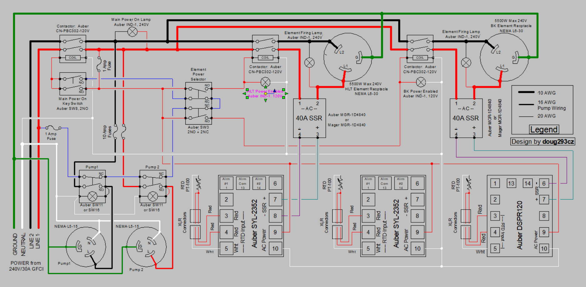
Here's the schematic that shows the improved "Safe Start" interlock. In this version, nothing can have voltage on it before the main switch is turned on, except the blue wires in the SS interlock.

HERMS for Video -Improved Safe Start.PNG


Brew on :mug:
 
Here's the schematic that shows the improved "Safe Start" interlock. In this version, nothing can have voltage on it before the main switch is turned on, except the blue wires in the SS interlock.

View attachment 678716

Brew on :mug:

Very Nice!!! It goes along with other designs I found from you in this forum. Now I will buy everything and see if I can build it.
I will use a contactor instead of that relay, because yes I want to keep it all in din rails.

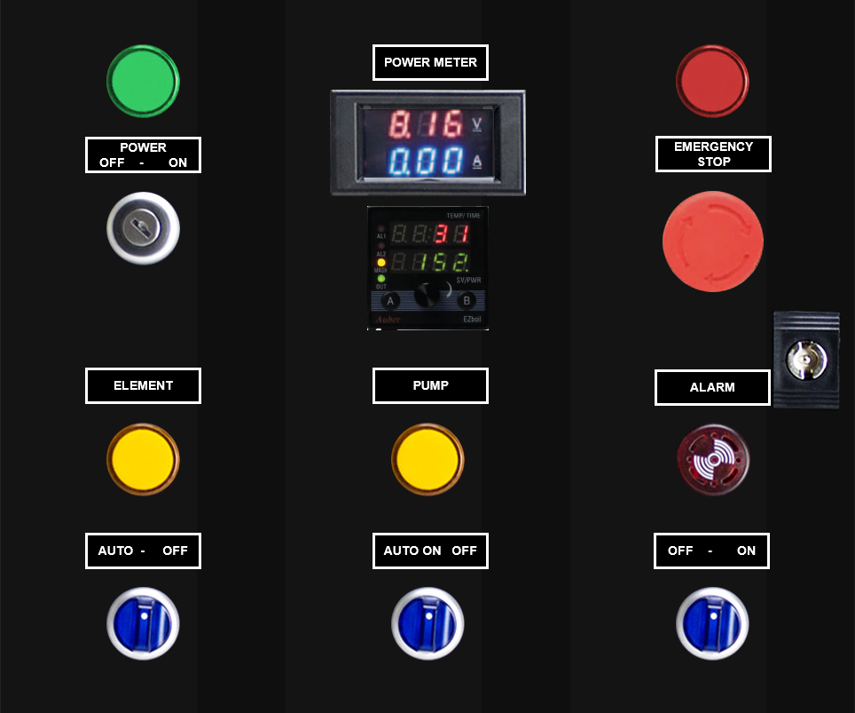
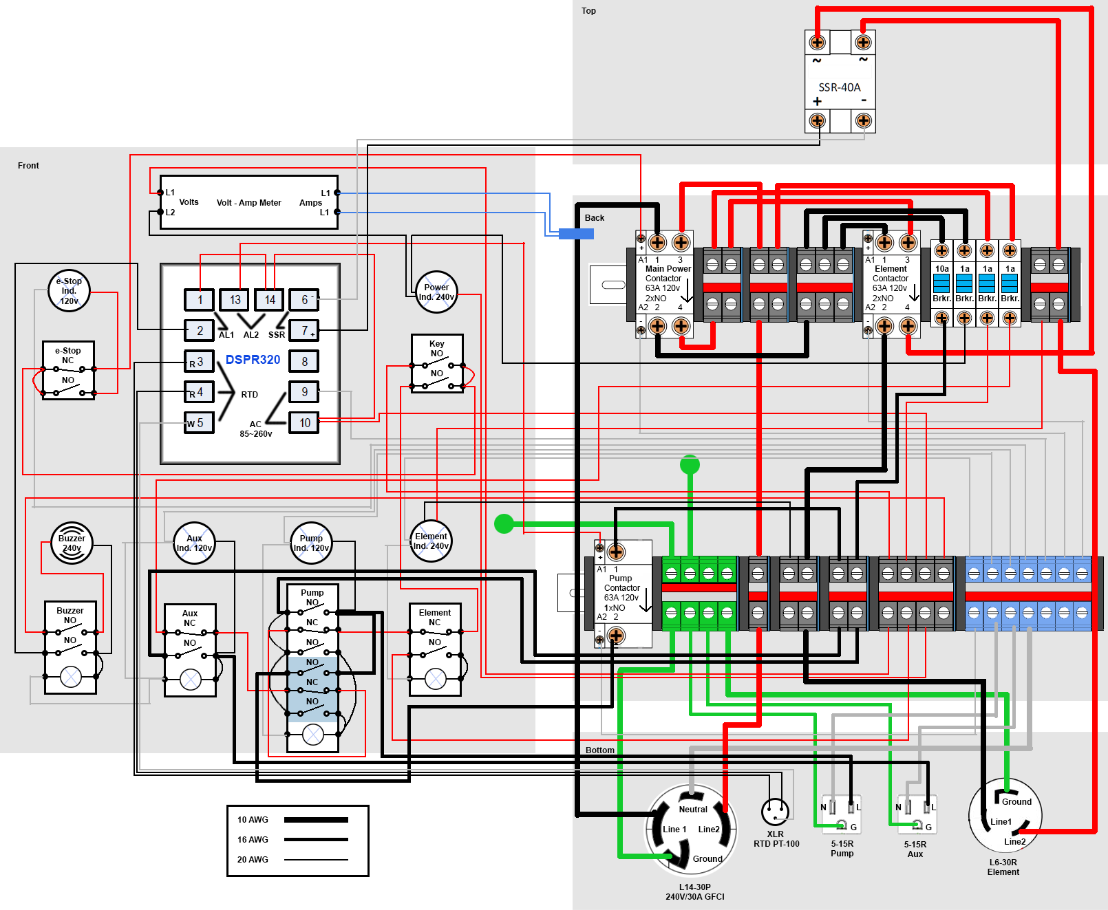
I started drawing in Photoshop the disposition of the components in the panel, and the wiring connections. That will make my life easier when it's time to assemble it. I will post the drawings here later when it's ready, just for the fun of it.

Thank you so much!!!!

Cheers!!!
 
Now, be prepared for a mess of wires :p
I have it in Photoshop with each color/gauge of wire in different layers, so to make it easier for the assembly.
I went with the additional blocks for the pump's 3 positions switch, so the light will always be ON when ON or Auto is selected.
I am just posting it here for the fun of it.

My-Panel-Mockup.png
My-Wiring-Diagram.png


Thank you again for all the help!
Cheers!
 
Last edited:
Cool idea! I could not see it very well cause the image is quite small. If I click on it I get a "page not fount" error...
Thank you!
Cheer!!!
I’ll have to revie the photo procedures today. I haven’t uploaded since the app went down. I added the direct link for you.

https://i924.photobucket.com/albums...ads/B1D7FDB6-E209-492B-BB1B-7B020A0B660A.jpeg
Basically the pump switch sends 24 VAC to the HLT grant low level float, to the pump relay coil, on to the Recirculate/Sparge mode switch, and at that point in either goes directly to the HLT grant high level float switch, or is first bypassed through the MLT float switch before moving on to the HLT grant HL float. The goal for me designing it this was to have pump run dry protection through the use of the grant, LL, and HL float switches. The MLT float allows for some automation to better control sparge water level without opening up the lid to keep an eye on it. All I do is manually set the drain valve on the MLT, and the MLT grant will operate the wort pump cycle IG it on/off. I will be adding some bypass switches for the floats in case they decide to fail during a brew session. This is one of the designs I’ve looked at to replace the float switches with conductive ones if they start to give me issues.

https://www.instructables.com/id/Build-a-simple-water-level-control/
Very cool!!!! Thank you for the picture! :)
 
Back
Top