I used my SS chugger for most of the day yesterday brewing up 20 gallons of tasty brew. The pump worked like a charm. soon i will buy another one when my stand gets a little closer to operational. for anyone who is still tossing around buying one of these i would say BUY IT!
You are using an out of date browser. It may not display this or other websites correctly.
You should upgrade or use an alternative browser.
You should upgrade or use an alternative browser.
New Replacement for March Pump
- Thread starter browjaso62
- Start date

Help Support Homebrew Talk:
This site may earn a commission from merchant affiliate
links, including eBay, Amazon, and others.
Cpt_Kirks
Well-Known Member
I need a SS head to replace my plastic head. What do they cost, I can't find one on ebay right now?

tjferris
Well-Known Member
Im sure glad you caught my sarcasm........
it was subtle but I did catch on
")
I need a SS head to replace my plastic head. What do they cost, I can't find one on ebay right now?
http://cgi.ebay.com/STAINLESS-STEEL-REPLACEMENT-HEAD-MARCH-809-PL-/320606933368
Make sure you rotate the head 180 degrees on the right pump.
pumps checking out their new home:

I am very Happy with the quality of these pumps and will post another full review once I get them wired up and pumping wort. For now they get 5 stars for service and build quality for a value price.

klyph
Well-Known Member
So it turns out mike shipped mine right away, I just got the tracking number and it's already in town. Seriously impressed with not only giving me a free product, but the speed in which he shipped to Alaska. Many kudos to Tri-State Pumps.
Thanks again mike, I'll post up my review soon.
Thanks again mike, I'll post up my review soon.


![Craft A Brew - Safale S-04 Dry Yeast - Fermentis - English Ale Dry Yeast - For English and American Ales and Hard Apple Ciders - Ingredients for Home Brewing - Beer Making Supplies - [1 Pack]](https://m.media-amazon.com/images/I/41fVGNh6JfL._SL500_.jpg)
$6.95 ($17.38 / Ounce)
$7.47 ($18.68 / Ounce)
Craft A Brew - Safale S-04 Dry Yeast - Fermentis - English Ale Dry Yeast - For English and American Ales and Hard Apple Ciders - Ingredients for Home Brewing - Beer Making Supplies - [1 Pack]
BellaRae


$20.94
$29.99
The Brew Your Own Big Book of Clone Recipes: Featuring 300 Homebrew Recipes from Your Favorite Breweries
Amazon.com


$53.24
1pc Hose Barb/MFL 1.5" Tri Clamp to Ball Lock Post Liquid Gas Homebrew Kegging Fermentation Parts Brewer Hardware SUS304(Liquid Hose Barb)
Guangshui Weilu You Trading Co., Ltd


$33.99 ($17.00 / Count)
$41.99 ($21.00 / Count)
2 Pack 1 Gallon Large Fermentation Jars with 3 Airlocks and 2 SCREW Lids(100% Airtight Heavy Duty Lid w Silicone) - Wide Mouth Glass Jars w Scale Mark - Pickle Jars for Sauerkraut, Sourdough Starter
Qianfenie Direct


$53.24
1pc Hose Barb/MFL 1.5" Tri Clamp to Ball Lock Post Liquid Gas Homebrew Kegging Fermentation Parts Brewer Hardware SUS304(Liquid MFL)
yunchengshiyanhuqucuichendianzishangwuyouxiangongsi


$172.35
2 Inch Tri Clamp Keg Manifold With Ball Lock Posts, Pressure Gauge, PRV (0-30 PSI) – Homebrew, Fermentation, Kegging System
wuhanshijiayangzhiyimaoyiyouxiangongsi

$58.16
HUIZHUGS Brewing Equipment Keg Ball Lock Faucet 30cm Reinforced Silicone Hose Secondary Fermentation Homebrew Kegging Brewing Equipment
xiangshuizhenzhanglingfengshop


$10.99 ($31.16 / Ounce)
Hornindal Kveik Yeast for Homebrewing - Mead, Cider, Wine, Beer - 10g Packet - Saccharomyces Cerevisiae - Sold by Shadowhive.com
Shadowhive


$22.00 ($623.23 / Ounce)
AMZLMPKNTW Ball Lock Sample Faucet 30cm Reinforced Silicone Hose Secondary Fermentation Homebrew Kegging joyful
无为中南商贸有限公司


$7.79 ($7.79 / Count)
Craft A Brew - LalBrew Voss™ - Kveik Ale Yeast - For Craft Lagers - Ingredients for Home Brewing - Beer Making Supplies - (1 Pack)
Craft a Brew
$176.97
1pc Commercial Keg Manifold 2" Tri Clamp,Ball Lock Tapping Head,Pressure Gauge/Adjustable PRV for Kegging,Fermentation Control
hanhanbaihuoxiaoshoudian


lamarguy
Well-Known Member
Make sure you rotate the head 180 degrees on the right pump.
And, avoid mounting the motor on its side (sleeve-bearing oil ports should face up). Makes oiling the motor less difficult.
tjferris
Well-Known Member
Make sure you rotate the head 180 degrees on the right pump.
Thanks, I do plan on taking it apart and rotating the pump head, as well as painting the pump cover. I don't have them mounted yet as you can see in the pic, I just tossed them up there to show what they looked like as soon as I ripped open the box
klyph
Well-Known Member
Make sure you rotate the head 180 degrees on the right pump.
Actually the pumps work best IMO with the outlets horizontal, the outlet facing right, the inlet facing left. This actually places the outlet opening of the impeller housing straight up allowing the air to be full purged from the pump.
tjferris
Well-Known Member
And, avoid mounting the motor on its side (sleeve-bearing oil ports should face up). Makes oiling the motor less difficult.
ohhh good point, I wouldn't have thought of that until AFTER i was cussing trying to oil them, I may have to rethink my mount.....
Cpt_Kirks
Well-Known Member
Those will work with the Chugger, right?
Freakin' ebay search sucks, I could not find that, even this morning!
Thanks.
Scut_Monkey
Well-Known Member
Those will work with the Chugger, right?
Freakin' ebay search sucks, I could not find that, even this morning!
Thanks.
The head is made by chugger pumps as a replacement for their actual pump. It has a description with the March 809 pump listed most likely to indicate that you can use it on a March pump as well.
BrewBeemer
Well-Known Member
My pump just arrived this morning, I got that Christmas morning feeling inside.
Thanks Mike for this great SS pump offer plus what's posted on ebay. I just need to power up this puppy and play. Again many thanks.
Thanks Mike for this great SS pump offer plus what's posted on ebay. I just need to power up this puppy and play. Again many thanks.
klyph
Well-Known Member
Just received mine yesterday, THANKS MIKE! I'll be posting a review ASAP.
knightbeer39
Well-Known Member
The head is made by chugger pumps as a replacement for their actual pump. It has a description with the March 809 pump listed most likely to indicate that you can use it on a March pump as well.
I replaced one of my March 809's heads with the stainless chugger head, and it works like a charm. And you don't have to look at that hideous green housing that way
BrewBeemer
Well-Known Member
Those will work with the Chugger, right?
Freakin' ebay search sucks, I could not find that, even this morning!
Thanks.
I just went to ebay, Chugger pump in SS with free shipping $99.99.
http://cgi.ebay.com/Chugger-Pump-St...580?pt=LH_DefaultDomain_0&hash=item33614567b4
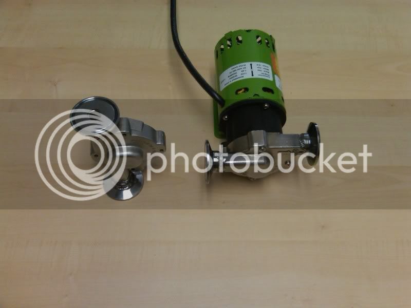
Just wanted to show what you can do with Mike's Chugger heads if you want. Mike sent me one of the SS pumps when I emailed him a couple of weeks ago and suggested that maybe he try to put triclover ends on them. He sent it to me for free and said try away. great guy. Ended up buying 2 more from him and have one more to convert.
I am not a skilled TIG welder, so I can't claim the workmanship. A local guy I have used who i think did a great job.
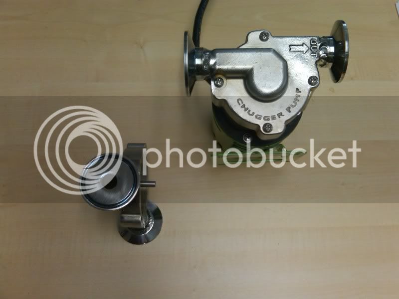
I am not a skilled TIG welder, so I can't claim the workmanship. A local guy I have used who i think did a great job.
klyph
Well-Known Member
Wow, I just posted about wanting to do exactly that. uncanny.
Though it looks like you used weld ferrules instead of the threaded adapters?
I'm thinking about getting 1/2" female NPT to triclamp adapters
And thread them onto the chugger pump head
Then have the adaptor sanitary welded at the face.
I'm not sure if this would give you a sanitary pump or not considering the internals, but it would eliminate contamination from threads.
Though it looks like you used weld ferrules instead of the threaded adapters?
DBbrewing
Well-Known Member
Got my pump yesterday and will give it a try this weekend, thanks Mike!
DakotaRules
Well-Known Member
Got my chugged this week also! Thanks to Mike for the pump head upgrade!  I won't get to try mine for a while as it was confiscated by my mother in law as a christmas gift. I have my toolbox made and wired just need to put the pump in it. Good thing I have plenty of beer made cause I won't be able to brew till after christmas.
Thanks again Mike!
I won't get to try mine for a while as it was confiscated by my mother in law as a christmas gift. I have my toolbox made and wired just need to put the pump in it. Good thing I have plenty of beer made cause I won't be able to brew till after christmas. Thanks again Mike!
klyph,
I figured I wasn't the only one wanting to give tri clover a try.
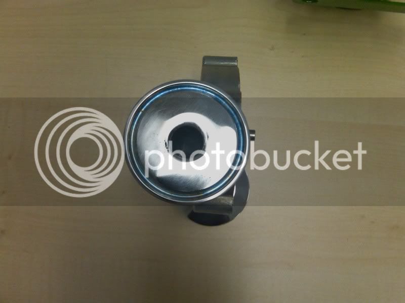
Your right that I used ferrules on the head to the right. I used end caps on the one to the left. Both turned out fine, but the ferrules version was easier to do. I also bored out the inlet side a little over 1/2".
The ferrules made it easier to keep the ends square to the pump and parallel to each other.
I thought about using the female NPT tri clover ends, but there was too much threads exposed after it was screwed on to be able to cover them with a smooth TIG weld on the inside. Maybe if they had a deeper cut threads, that would eliminate that problem.
I figured I wasn't the only one wanting to give tri clover a try.
Your right that I used ferrules on the head to the right. I used end caps on the one to the left. Both turned out fine, but the ferrules version was easier to do. I also bored out the inlet side a little over 1/2".
The ferrules made it easier to keep the ends square to the pump and parallel to each other.
I thought about using the female NPT tri clover ends, but there was too much threads exposed after it was screwed on to be able to cover them with a smooth TIG weld on the inside. Maybe if they had a deeper cut threads, that would eliminate that problem.
klyph
Well-Known Member
I thought about using the female NPT tri clover ends, but there was too much threads exposed after it was screwed on to be able to cover them with a smooth TIG weld on the inside. Maybe if they had a deeper cut threads, that would eliminate that problem.
Good to know, thanks!
BrewBeemer
Well-Known Member
Will the FMT Tri fitting tighten up if screwed down enough?
If so measure how much is sticking thru then cut it off, install
the Tri again then Tig it on the inside.
If so measure how much is sticking thru then cut it off, install
the Tri again then Tig it on the inside.
BrewBeemer
Well-Known Member
I also bored out the inlet side a little over 1/2".
I'm limited at the time to move and inspect my pump more than looking at it. On my Chugger the inlet is .456" ID or 83% of cross sectional area of .500" ID tubing. On the discharge .424" ID or 71.9% of .500" ID tubing.
On the inlet should anyone open it up to .500" or more there is a relief cut for the pump mounting screw that will make the wall thickness an issue to consider before drilling it out, breaking thru the wall would be a pisser or leaker. Later if able i'll take a lookie inside.
I did notice a strong machining oil smell left on the casting as well inside the pump, this would need to be taken apart and washed before placed into service.
BrewBeemer
Well-Known Member
On the pump the MPT inlet especially if your using a coupling the fluid flow will go from .875" to .455" at the flat end of the pump inlet, this will create a large turbulence point. My suggestion is to countersink the inlet ID until the outside of the CS is just touching the last of the faced off inlet surface for a smoother fluid transition. Every turn, bend and fitting adds turbulence to the flow not counting tubing friction, it all adds up to reduced pump performance output.
I just got inside my pump, the side inlet port from the housing to impeller is "D" shaped, width of .890", the impeller cast center post .490" diameter.
The pisser my pump has stainless flashing at the end of this center post like a mushroom a diameter of .620". This alone is a grain and crap snag location besides causing turbulence as well restricting impeller inlet flow.
Looking into the inlet port there is a ramp with a step that also that can be smoothed down for a smoother fluid transition, possible reduction of pump harder to get primed is my thinking on the above mentioned. The side of the impeller to inlet port is a rather wide gap causing fluid to bleed past vs caught in the impeller and centrifuged out to the discharge port. Again my thinking here to up the pump's efficiency from the standard production design, it all adds up and can only help.
Adding to this there is quite a lot of impeller end play which increases bleeding across the input port vs shearing and pumping out, my pump this gap is .140" wide when the impeller is against the stainless cover plate.
I also found I was able to slide the motor magnet out an additional .094" just clearing the stainless cover, this allows the impeller magnet to just float touching the inner side of this stainless end cover reducing the pulling of the two magnets when they are not inline magnetically. I see this as less end thrust pulling wear plus deeper engagement of the drive to driven magnet in strength for a stronger impeller pulling before the magnetic coupling drive starts to slip.
I have a wild idea, narrow down both sides of the housing for less fluid bleeding down off the sides of the impeller blades making the pump more like a positive displacement in function plus chamfering and blending the inlet and outlet ports. Later on i'll first do NIB flow numbers then redo testing after reworking the pump to see if any actual number differences. I must move around back's killing me just typing this.....=o&o>........
I'm planning a build and have a few questions about these pumps and fluidics systems.
Are Chugger and March pumps subject fluid drift when not powered?
In other words: Does the pump act as a valve? Will a positive pressure on the inlet cause fluid to move through the pump when not running?
Inversely, does the pump act as a check? Will a positive pressure on the outlet cause fluid to move backward through the pump when not running?
Topic morph: Has anyone used check valves in their fluidics routing systems? Ball checks often have a cracking pressure that must be exceeded before flow begins in the operating direction. Does this limit your minimum flow in practice? I don't believe it should because you can maintain flow volume with higher pressure by decreasing exit orifice, thus increasing velocity. Should this be a concern? Flap or gate checks likely have lower cracking pressures, anyone use these or have any insight they can share?
Tim
Cpt_Kirks
Well-Known Member
Can't speak for Chugger but with March, fluid will freely flow through. You'll need a valve to stop flow when pump is not in use.
The Chugger works the same way.
BrewBeemer
Well-Known Member
With the ability to swap out a March to Chugger pump head plus both being centrifugal by design no way as they will backflow they are not positive displacement pumps. Your dealing with a shutoff of 3.31 PSI on ther Chugger pump, spring loaded check valve will reduce the output PSI besides leak if any particles get under the seat.
Similar threads
- Replies
- 1
- Views
- 826
- Replies
- 4
- Views
- 1K
- Replies
- 0
- Views
- 1K
- Replies
- 8
- Views
- 2K
- Replies
- 6
- Views
- 1K
