Got the 25a 240v plugs that auggie uses. Love these things and they were super cheap....
But, I planned on using these to feed power from the control panel to the heater elements. The jack side has male connectors, which is not safe. Especially if I'm planning on leaving the HLT element empty for a little while (which I am)....
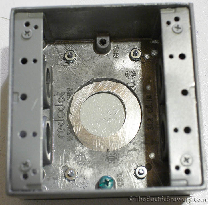
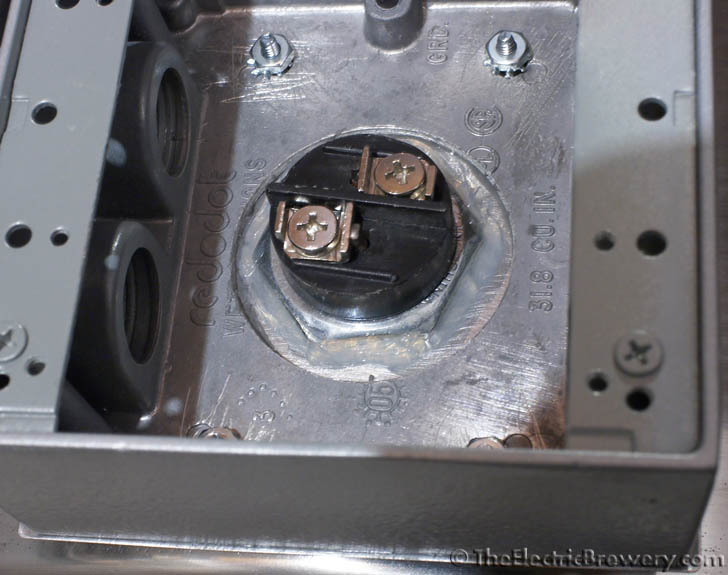
But, I really like the idea of having these on the element side in the 3/4" hole of the red dot box like this
I'm going to try and grind the threads out of the box to see if the jack will slide through from the inside. Now I just need to find some cheap connectors for the control panel side...


")


