New BruControl Build

Homebrew Talk - Beer, Wine, Mead, & Cider Brewing Discussion Forum

Help Support Homebrew Talk - Beer, Wine, Mead, & Cider Brewing Discussion Forum:

This site may earn a commission from merchant affiliate links, including eBay, Amazon, and others.
Electricity scares the cr@p out of me. I'm definitely going to hire a licensed electrician to review all my work etc.

Learning about it will take away the fear...at least it should. The good thing about electricity is that it's predictable and controllable. Start by learning the basics: What are Volts, Watts, and Amps, and what are the basic formulas (E=IR, etc.). Learn the rules that cover the relationship between Amps and AWG. Learn the difference between ground and neutral. Finally, learn as much as you can about safety practices. Feel free to ask questions!
 
Was rereading this thread in preparation for rebuilding my system with Brucontrol to replace my original BrewTroller and found one of your statements curious; “This design is original, it’s mine, and I don’t want anyone to copy or use it for commercial purposes without my permission.” Your schematic looks like many others I’ve seen, you’re using commercial software and hardware, using readily available equipment, and your illustrated equipment layout is typical. Are you planning something not shown? I don’t mean to start a fight but I’m not seeing anything unique let alone proprietary.
 
@TexasWine , it's plodding along like a herd of turtles, but I made some progress today (finally). Washed out the kettles with TSP to get any residual oil and metal shavings from cutting holes. Assembled everything and put 20 gallons in each kettle to check for leaks. I'm stunned to report there were none. O-rings are my new best friend.

After the static tests, I jumped back in on the panel wiring. Started with what I think is the hardest part, the stacked 4-relay boards (pics attached). I've ordered some triple stack 2.5mm Phoenix blocks to create a +12VDC bus next to the power supply. I don't have much room, hence the high density blocks. I'm also going through and appending my drawings with the wire number as I go along, which slows everything down some more. I'm unwilling to rush through this part of the build. If I do, it will be a b**ch to work on it later. The output leads are going to go into a panel-mount 12-pin Deutsch connector, and from there into a junction box close to the valves.

I'll keep pecking away at it, and spend some time building out the stand. I need to build a face panel on the stand from the lower shelf to the kettle shelf. That's where I'm going to mount the pumps and valves. I'm not sure if I'm going to use plywood or aluminum yet. The plywood will take a lot more labor to finish properly, but the aluminum will be a lot more expensive. I'm also thinking of hinging it along the bottom, so I can mount everything on the back side and drop it down for service. It's the design-as-you-go approach, which I'm not a fan of, but I just have to dig in and start building to see how it will work out.

IMG_1095.JPG IMG_1096.JPG 46198_1000_int_04.jpg
 
Another update from the weekend...Kept chugging along on wiring the panel. This is a phase of the build that I'm refusing to rush through. I really don't want to see a couple hundred bucks disappear in a flash of light and a puff of smoke when I flip the switch. I got the control side of the relay boards wired up, and the same with the RTD board. I have a few more leads to go on the Mega board...the 12VDC power supply and the grounds.

I still have to add the wires for the PT-100 sensors to get from the cable entry point to the RTD board. There are still some power leads and a bunch of grounds and neutrals to sort out, then I have to run the leads to the door for the E-stop, on/off switch, meters, and pilot lamps.

Before I do that, I'm going to pop the backplane out of the enclosure and cut holes for the skintops, Deutsch connectors, and heat sink. By the time I get done with the enclosure, the valves should have arrived, and I can get on with rigging the stand.

I am thinking seriously about switching from the Ethernet shield to the WiFi shield with the external antenna. Yes, it will be a bit more spendiness, but I think the simplicity will outweigh the cost.

IMG_1103.JPG
 
I am thinking seriously about switching from the Ethernet shield to the WiFi shield with the external antenna. Yes, it will be a bit more spendiness, but I think the simplicity will outweigh the cost.

There are pros and cons with both but my experience with wireless is 100% positive. I have 6ms ping from BruControl to the Feather which is as good as wired. AFAIK they use the same WINC1500 chip
 
Probably a silly question but will you still need to mount ssr’s in your panel? I have a Kal clone that I built myself and am somewhat intimidated by all of the additional hardware I see in your panel, appears to be mostly breakers and such but considering I’m a novice to the automation side the pictures scare me a little. I run a 3 vessel herms system, all electric.
 
Think of it this way... the controller replaces dedicated PIDs, switches, and LEDs (the cover panel can remain blank, and all the controls are on a monitor instead). The rest is all the same, including the SSRs. In fact, many will argue an automated system is easier to wire.
 
@BigDog007 I concur with @BrunDog above. My schematics got a whole lot simpler when I switched from a straight Kal clone to a BruControl system. The complexity I added has more to do with adding 7 electrically-operated valves and PT100 temp sensors (vice 2-wire) than it does with controlling the elements and pumps. Also, adding PID controllers and switches to the door really jacks up the number of wires that have to go to the door. I still have two voltmeters, a couple of switches, and some indicator lights, but it's a lot less than Kal's panel.

A lot of the additional hardware you see in my panel is because I opted to add what I feel is the overcurrent protection (fuses and breakers) that is missing from Kal's design. I also opted to use Phoenix contact blocks instead of open screw terminals. In my mind, there is less risk of accidental contact with a live terminal that way. @BrunDog and I are still having a running skirmish regarding proper overcurrent protection, but I continue to have hope that he'll see the light. :)

At the end of the day, there are fewer components and less wiring in my panel than there would be if I built a Kal clone, so don't get stuck on the idea that a BruControl/Arduino system is more complex. It really isn't.
 
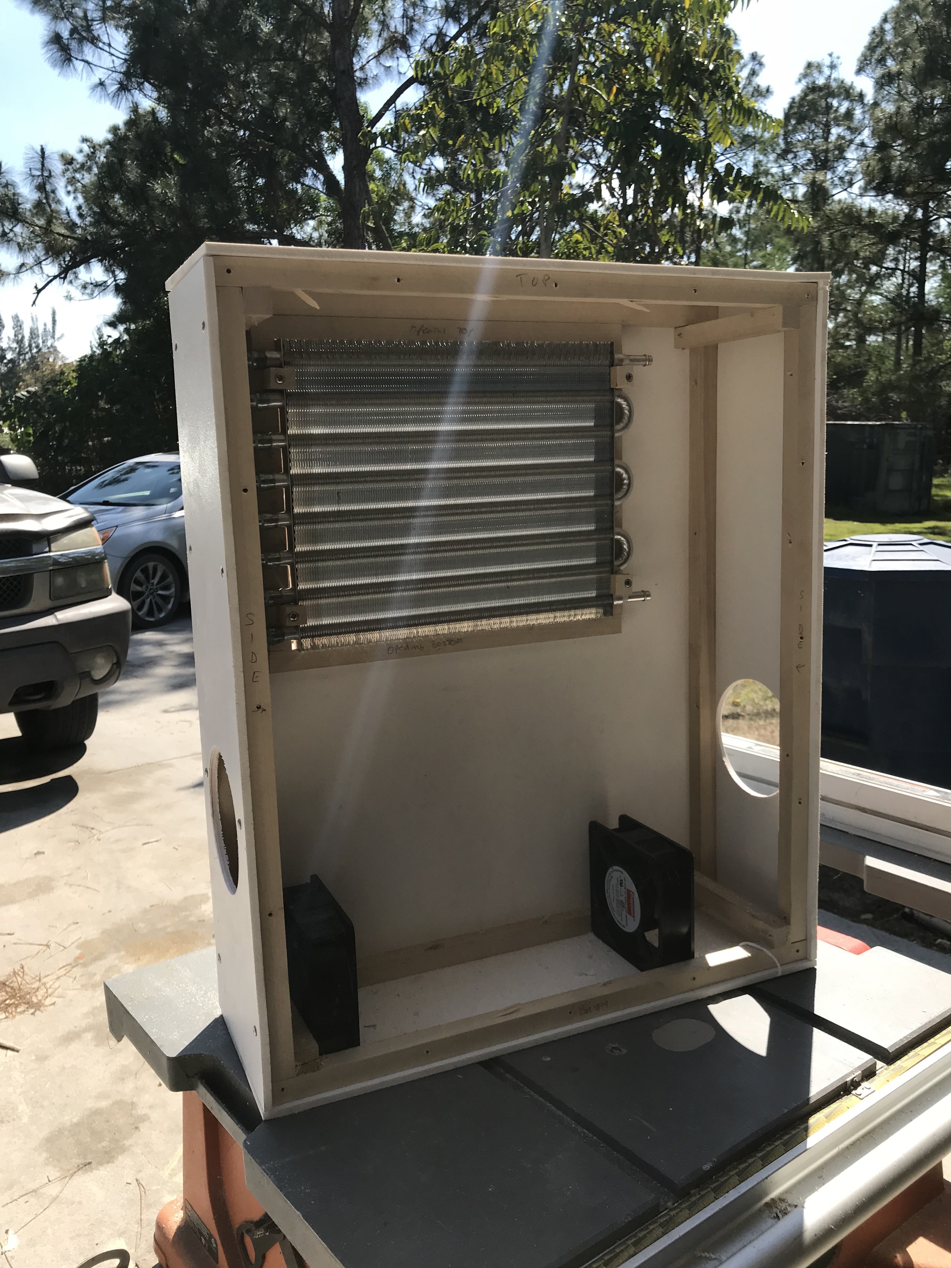
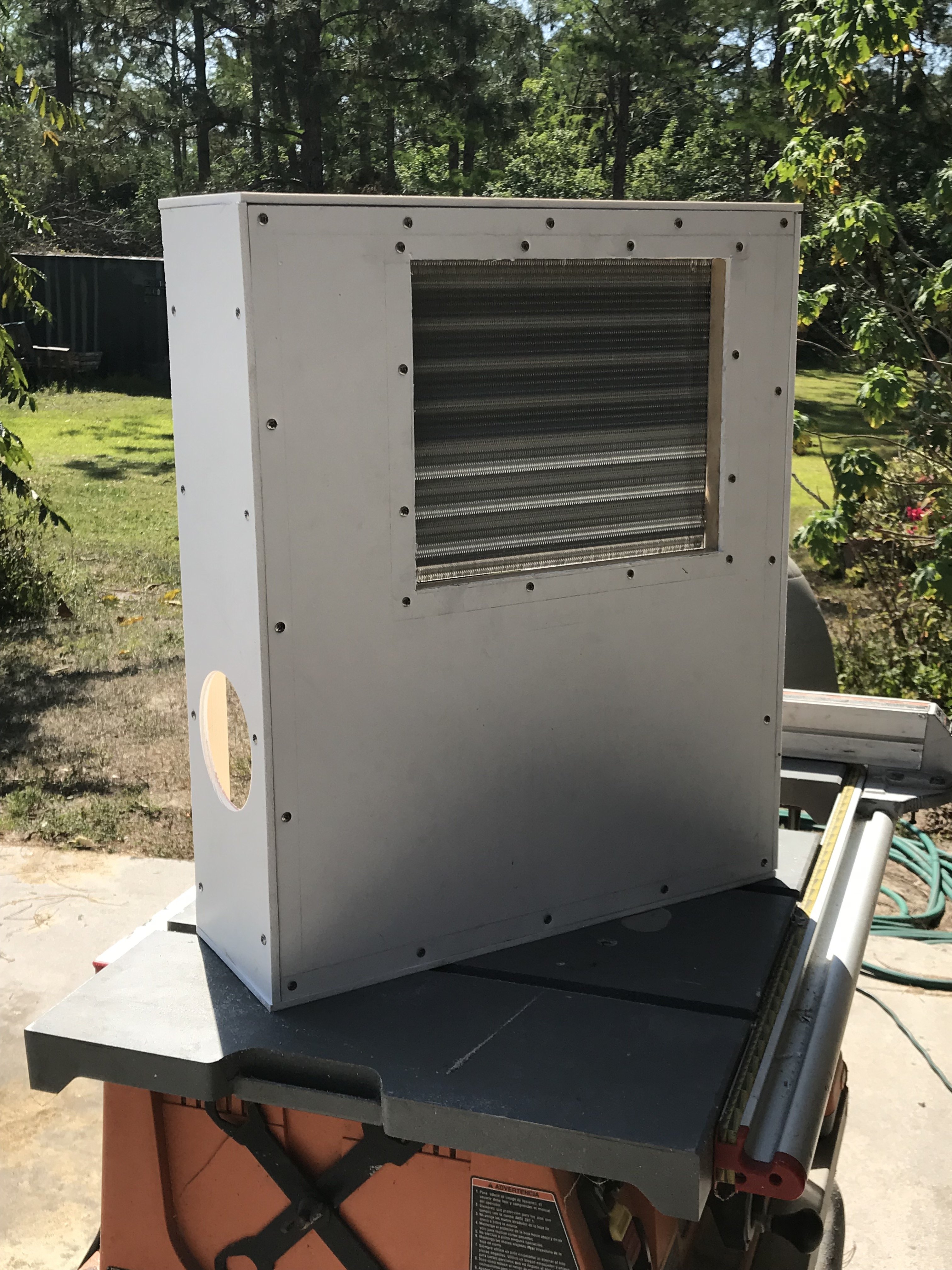
Quick update: The big hole in the enclosure has been cut, and the heatsink and SSRs are mounted. I'm still waiting on the Deutsch connectors to arrive sometime next week. Just to keep me humble, the beer gods broke a tap in the last hole. Rrrrr.

I also received my order of glycol, so I fired up the chiller and filled the reservoir. I had a bit of a hiccup when I fired it up, though. The compressor is mounted on a lift-up lid that covers the reservoir. Apparently, when cleaning it out and filling it, some of the oil in the compressor got where it isn't supposed to go. When I started it, it would run for about 30 seconds, the bog down and shut off. A friend of mine is a retired gas passer (HVAC genius, actually), so I asked him to come over and look at it. In the six days between phone call and visit, everything must have settled, because it ran like a champ. The system pulled 11 gallons of glycol solution from 78F to 18.5F in about three hours.

Ultimately, I will wind up adding thermostatic control to the reservoir, because at 18.5F, I was getting condensate freezing up on the suction line all the way back to the compressor. I'll have to strike a balance once I see how well the system handles the heat load from the returning glycol solution.

I bought a transmission cooler from Amazon that I am going to use as glycol solution loop to chill my fermentation chamber. I have a couple of 105 CFM muffin fans, so I'm going to build a plenum chamber on the hot side of the transmission cooler. I'll mount the fans to the plenum, which will force air across the coils. Again, it will take some tweaking, and maybe even a second coil, but I think it will work well. I'll also have to integrate a condensate drain of some kind.

The paths for these projects are starting to converge, and I'm getting pretty close to being done. My wife has been watching the work I've been putting in, and is happy that I've kept the rest of the chores around here up to date, so she dropped a little surprise on me yesterday...A couple of stainless steel work tables she picked up on the cheap from one of her clients. The larger is a standard countertop height, but the small one is much lower, putting anything on it at a really comfortable height to work on.

IMG_4527.JPG IMG_6806.JPG
 
Last edited by a moderator:
Progress update: This past weekend, I finally built the heat exchanger for the fermentation chamber that's been sitting around unused. Originally, I built it to mate to a donor fridge, but the donor crapped out about two weeks after commissioning. I removed the framing to mate to a donor and closed off that end of the box. I've been puzzling over the design of a heat exchanger, and finally settled on a box fabricated from 3/4" x 3/4" poplar cleats and 1/4" PVC sheeting. Attached is an old pic from when I was building the chamber, as well as a couple of pics of the heat exchanger. All I have to do now is connect the hoses and wire the fans.

I also just found out that I'm still a week away from receiving the last two Deutsch connectors I need to finish cutting holes in the control enclosure. I think I'm just going to measure it out from the Deutsch AutoCAD files and start cutting. I really want to get the back panel back into the enclosure and finish up the wiring.

I also picked up a sheet of 1/2" birch plywood to make a skirt panel for the front of the stand for mounting pumps and valves, and to make a foundation for the control enclosure. I didn't get to that project this weekend, so I'm still trying to work around a full sheet of plywood in my increasingly cramped garage. I really need to do a major intermediate cleanup!

IMG_1274.jpg
 

Attachments

  • IMG_1278.JPG
    IMG_1278.JPG
    1.8 MB · Views: 328
  • IMG_1280.JPG
    IMG_1280.JPG
    1.6 MB · Views: 351
  • IMG_1284.JPG
    IMG_1284.JPG
    1.4 MB · Views: 338
210 CFM right now. For $37, you don't get airflow specs with your add-on transmission cooler. It will be trial and error. I built it with room enough to add another cooler, or to add additional fans. Coil icing, condensation, and thermal transfer efficiency will have to get looked at pretty carefully to develop set points and hysteresis bands for the glycol reservoir temp and for the fermentation chamber. The graphing capabilities of BruControl should be a huge help.
 
Major progress this weekend. Started with cutting and fitting the plywood for the lower shelf face skirt and for the foundation for the enclosure. With the sheet of plywood finally out of my way, I had room to work on the enclosure. I cut the holes in the bottom, deburred them, and then reinstalled the back panel into the enclosure. With the cable entry glands and the Deutsch connectors in place, I could finally finish up the wiring.

Fortunately, Some quick tech support with @BrunDog saved me some hours of frustration and rewiring, as I had made some incorrect assumptions about the electric valves that I ordered. I was particularly off on the proportional valves. I spent part of yesterday reconfiguring and rewiring the relays. In the afternoon and evening, I sat down and updated all of my schematics and drawings. I cobbled a pinout diagram for the three 12-pin Deutsch connectors, and I'm really glad I did. It made the hookups dead easy today.

Once I got the control wiring all squared away this morning, I started in on the power distribution, SSRs, and the pump wiring. Once that was done, I wired the door. The final step was to pop the covers on the tray to hide the spaghetti.

Tomorrow, when I'm less tired and not so close to the project, I'll start doing some more continuity testing, then light it off. I have to mount a J-box behind the skirt board. Once that's done, I can mount the pumps and temp sensors. At that point, I should be able to start running some water-only brews. Valves will have to be added after the slow boat from China finally docks.


IMG_1326.JPG IMG_1329.JPG IMG_1330.JPG
 
Last edited:
Really enjoying this thread.

Has your schematic changed at all since your original post? Thought I saw some additional relays. Also interested in your part list mainly, not sure if you have been tracking a master BOM or anything.

I'm trying to brainstorm a little on how to make a similar control box smaller. Had an idea of using two boxes, control side / hot side.

I'd have similar goals to yours, but I'd likely have 3 10-15gal kettles instead of your 30gal vessels.
 
Has your schematic changed at all since your original post?

Good Lord, yes! Some notables:
  • I added a 24VDC 30W power supply for the proportional valves.
  • I split the power feed to the relay boards into a 5V feed to run the opto-isolators and a 12V feed to run the relays (h/t to @BrunDog).
  • I was able to eliminate 2 PLC relays, because I didn't notice that the blue relays could switch 120VAC.
  • My door wiring is still in flux. I need to move to DPST switches for the E-stop and On/Off switch. Power is leaking through the meters and keeping the contactor pulled in even with the E-stop open!
  • Again because I didn't study the valve cut sheets closely enough, I had to add a NC lead from each valve relay out to the J-box.
  • I had to shift a couple of Arduino ports around to accommodate the PWM signal requirement for the proportional valves.
  • I added two low-current (5A or less)120VAC circuits to the stand (small fans and perhaps some LED lighting).
  • I added cabling for two flow meters I think I'll add sooner rather than later.

I'm sure there are others, I just can't think of them at the moment. I have a preliminary BOM that I need to start updating.
 
Last edited:
Another update...

Switching to double-pole actuators for the E-stop and the key switch fixed my meter leakage problem. Now the door is behaving as it should, and the contactor releases when it should. With that little issue out of the way, I turned my attention to the J-bx that needs to got on the back side of the skirt board, somewhere near the center of the rack. I mounted the 20A 4-prong twist-lock receptacle in a small emclosure, added a little DIN rail, and popped in a few Skintops. I'll finish filling the DIN rail, but it should work out OK. I installed a 20A 4-prong twist-lock plug on the end of the pump cable, so it's an easy plug-in for the pumps. The line cords for the pumps, the PT-100 wires, and the 3 12-conductor control cables all enter the J-box through Skintops. Once the valves arrive, that's 7 more 3/8" Skintops that have to get mounted.

The last thing I did today was to put the Deutsch plugs on the three control cables. Tomorrow, I'll add the remaining Skintops and hook up the pump and temp sensor wiring. I don't want to mount the box, the pumps, or anything else on the skirt board yet until the valves arrive and I can dummy the whole thing up to see how it's going to fit. But, with the pumps and temp sensors online, I can start water testing!

IMG_1333.JPG IMG_1334.JPG IMG_1335.JPG
 
I didn't get as much done tonight as I wanted to, but I did finish the J-box for the stand. I also connected the control cables that go to the J-box and started neatening up the cable spaghetti.

Next, I filled the kettle thermowells with the thermal paste I used underneath the SSRs and installed the temp sensors. I used a turkey marinade injector. There is a possibility that I may have wrecked it for future culinary use.

I decided to put bullet connectors on the temp sensor leads so I can take the kettles out of the rack for a deep cleaning without too much fuss and bother. The problem is that the 26 or 28 AWG leads are too small for all my strippers, so it's extra slow going to strip the insulation without compromising the conductors. Also, the bullet connectors I have are heat shrink connectors. At max. shrink, they still aren't touching the wire, so I carefully squeezed the heat shrink with a little pair of flat-jawed pliers as the adhesive hardened back up. It seems to have worked. Worse comes to worst, I'll put spade terminals back on and mount a little terminal strip behind the skirt board.

The last thing I did was to plug the power cord in and start running some continuity checks for ground. I clipped one test lead to a door latch, and started probing around. i was most concerned about the kettles, but they have 0Ω resistance to the latch. Same with everything I checked, except...

I'm going to have to run a bunch of green jumpers all over the place to ground the rack. It has these stupid little plastic wedges that set the shelf height. Unfortunately, the manufacturer didn't have the common damn courtesy to use conductive wedges, so now I have to run jumpers to each leg and to each shelf. I may cheat and just drill and tap the legs, and use a nut/bolt/fender washer clamp for the shelves. Tacky and ugly, but effective. And better than flopping around on the garage floor, wishing I could administer an AED to myself.


IMG_1337.JPG IMG_1338.JPG
 
I started hooking stuff up today. Temperature sensors seem to me to be the most critical, so I started there. I found one pin in a Deutsch connector that wasn't seated properly and fixed that, but I am still getting some wild readings from one of the three PT100 temp sensors I have in the system. There are about four or five points in the circuit that I can use to isolate the problem, so it's just a matter of being methodical and patient. Here's a 5-minute graph of a 60-90F band. All sensors are at ambient garage temperature. The HLT and MLT are rock solid, and reading consistently with my Fluke meter. The BK is another story....

Screen Shot 2018-04-13 at 11.16.00 PM.png
 
Bad PT100?
I've been troubleshooting and testing, and haven't run it to ground yet. The PT100 is OK. The wiring between the PT100 and the RTD amplifier is OK. The Mega port is OK. The RTD amplifier board is OK. The only thing suspectable at this point is a platform board, but the odds of that being bad are thin. If I can't isolate it in my next go-around, I'll toss out all of my previous results and start from scratch.
 
Brundog, I know you posted this before but I can't seem to find it. What are the pro's and con's of each of the temperature sensors that are compatible with BruControl? Thanks
 
I started hooking stuff up today. Temperature sensors seem to me to be the most critical, so I started there. I found one pin in a Deutsch connector that wasn't seated properly and fixed that, but I am still getting some wild readings from one of the three PT100 temp sensors I have in the system. There are about four or five points in the circuit that I can use to isolate the problem, so it's just a matter of being methodical and patient. Here's a 5-minute graph of a 60-90F band. All sensors are at ambient garage temperature. The HLT and MLT are rock solid, and reading consistently with my Fluke meter. The BK is another story....

View attachment 566045
I use all three types of temp probes and I have a similar issue with my rims pt100 which I have narrowed down to some sort of ground loop or electrical noise interference. I know its noise related because when my fermentation control panel and chiller are on at the same time as my rims element its unusable as it spikes to -212 and often stays there while the chiller pump or heaters are running. (They are on the same power 240v power circuit and I normally turn it off while brewing) I tried swapping probes and different isolated dc power supplies to power the ardiuno but in the end I found the issue stays with the physical rims mounting location for me regardless of swapping everything else including rtd ports on the panel and probe/wiring. I have triple checked and even ran temporary auxiliary grounds to the rims.

I have the same issue with a one wire temp sensor I tried to use to sense my chiller bath temp. brundog recommended using a capacitor as a filter which helped a lot but it still spiked randomly from time to time for a second.. My thermister board with stc sensors work flawlessly along with my other three rtds
 
Last edited:
@augiedoggy... what do you specifically mean by physical mounting location? IIRC you are not using the platform, so can you elaborate? We need to figure this out.
meaning mounted in the rims tube... It does not matter what rtd I mount in the end of the rims tube or what port in my control panel I plug it into. I have put my meter on the rims looking for some sign of voltage leak, nothing, and like I said Ive even redone the grounding to ensure its solid.

I was actually wondering if the long single pole element /rims design itself in relationship to the probe being mounted like 1/2" from the til could be causing some sort of electrical interference.. kind of like wrapping an extension cord around a copper pipe in a basement ceiling can create a "transformer" of sorts which Ive been told electrifies the pipe so I was told from the electrician who grabbed said pipe.... I wish I know more about this honestly..
 
Last edited:
@augiedoggy, do you have all of your 0V stuff on a common bus? I have my AC grounding and DC negatives (12, 24, and 5V) sharing a common bus that is referenced to the main house ground. I have the AC neutrals on a separate bus, but it is referenced back to the main house ground at my main distribution panel.

Also, while troubleshooting this problem, I have connected the "bad" RTD to a known good sensor, and the problem moves. The only constant is that anything connected to RTD1 header on the platform board shows the anomaly. I thought I was going to work on it some more last night, but life intervened. Pleasantly, in this case, but still had to put it off for a day. I'll report my findings tonight.
 
Update: It seems that the platform board has a fault of some kind. When I removed the RTD amp and ran jumpers from the RTD amp pins to the screw terminals on the platform board (bypassed the headers and traces), everything stabilized. I have already contacted @BrunDog for a replacement. Once I have the replacement in hand, I will run some tests on the board to see if I can tell what actually happened.

Next, I need to take a look at the total resistance between the RTD amp and the PT-100s. One of the PT-100s needs a heavier linear offset than the others, so there may be a resistive connection somewhere.

In other good news, I think my valves will be in hand by the weekend. Time to lay out the skirt board and put the plumbing together!

IMG_1379.JPG Screen Shot 2018-04-18 at 8.37.01 PM.png
 
@augiedoggy, do you have all of your 0V stuff on a common bus? I have my AC grounding and DC negatives (12, 24, and 5V) sharing a common bus that is referenced to the main house ground. I have the AC neutrals on a separate bus, but it is referenced back to the main house ground at my main distribution panel.

Also, while troubleshooting this problem, I have connected the "bad" RTD to a known good sensor, and the problem moves. The only constant is that anything connected to RTD1 header on the platform board shows the anomaly. I thought I was going to work on it some more last night, but life intervened. Pleasantly, in this case, but still had to put it off for a day. I'll report my findings tonight.
I have all my 5vdc stuff powered of shared terminals on a breadboard at the moment but have tried various experiments isolating and even powering it all off different dc power supplies including one powered off a different circuit. my 16 channel relay board has its own step down transformer to make 5v from 12 which I also tried with no change in behavior..
 
Sorry @GParkins! New platform in the works. I will report the result of the investigation to see where the issue is occurring. The board is passive so issues should be very rare. I suspect a bum header, since the terminals work ok with the other amplifiers. A bad solder joint is possible but not likely and Geoff re-flowed them. Also a broken trace on the board is highly unlikely.

Either way we’ll make it right!
 
Back
Top