need help asap plz!

Homebrew Talk - Beer, Wine, Mead, & Cider Brewing Discussion Forum

Help Support Homebrew Talk - Beer, Wine, Mead, & Cider Brewing Discussion Forum:

This site may earn a commission from merchant affiliate links, including eBay, Amazon, and others.

bagpiperjosh

Well-Known Member
Joined
Jan 19, 2012
Messages
343
Reaction score
1
Location
Plum
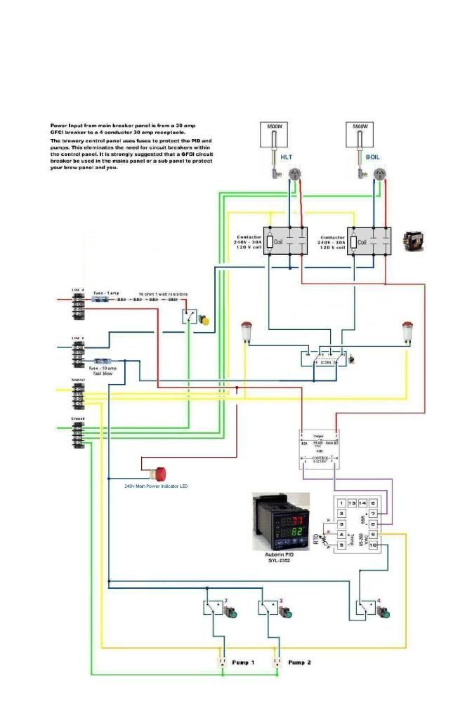
im trying to brew my 2nd batch on my 1 pid 2 element system, and i cant get the elements to turn on. when i put the 3 way switch to the left or right, it flashes sometimes and does nothing... if i unplug the power to the element the light will turn on... any idea?

EDIT:

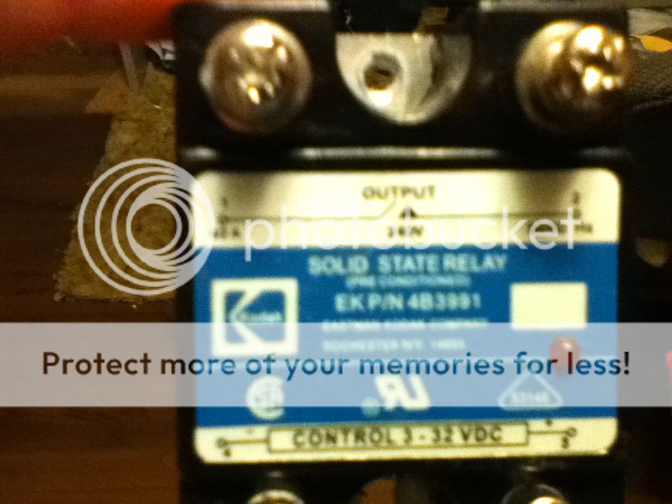
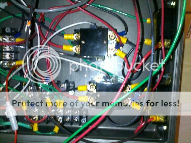
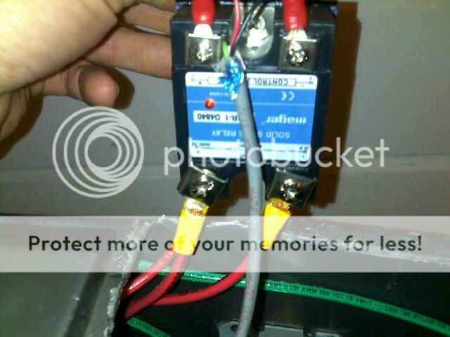
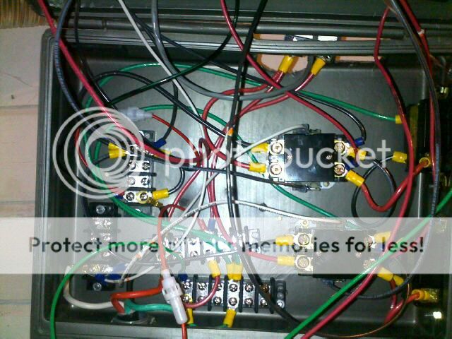
i think i had two wires backward. but now the water started to heat then the element would shut off... i think its a bad SSR.. i had 2 and the first one i think over heated and went pad. so i replaced it with the other one and that one worked to make my 5 gal batch, but now its doing the same thing... i have it externally mounted with a heat sink and thermal compound. has anyone else had this problem with SSRs going bad so often?
 
can you post a wiring diagram of how you have it connected to the load and power source? Also, I had those 2 way and 3 way switches burn out on me before so all i had to do is replace them. It's been running great ever since.
 
can you post a wiring diagram of how you have it connected to the load and power source? Also, I had those 2 way and 3 way switches burn out on me before so all i had to do is replace them. It's been running great ever since.
the only thing that is different in my setup is the kind of switch(mine looks like the one kal uses) and i dont have pumps yet
My_Panel_Schematic2.jpg
 
Can you post a picture of your SSR/heat sink mounting. If you have it mounted inside the panel with no airflow then it might overheat. Otherwise you should be fine since you used thermal paste. Also where did you get your SSRs from? I don't trust the cheap Chinese POS electronics.

Since you were able to brew a batch already with this setup it doesn't sound like its a PID setup issue otherwise it wouldn't have worked the first time.

Sounds like its time to bust out the multimeter and start checking voltages.
 
crane said:
Can you post a picture of your SSR/heat sink mounting. If you have it mounted inside the panel with no airflow then it might overheat. Otherwise you should be fine since you used thermal paste. Also where did you get your SSRs from? I don't trust the cheap Chinese POS electronics.

Since you were able to brew a batch already with this setup it doesn't sound like its a PID setup issue otherwise it wouldn't have worked the first time.

Sounds like its time to bust out the multimeter and start checking voltages.

Its externally mounted, but i did buy them off of ebay. They say kodak on them so i figured they would be fine. But i guess you never really KNOW when it comes to ebay
 
I have the eBay kodak ones and have had no problems. I ran them for over 24 hours straight once without issues. I use a huge 2lb copper heatsink from a hard drive. It cools much better than the crappy aluminum ones they come with on eBay.
 
JRems said:
I have the eBay kodak ones and have had no problems. I ran them for over 24 hours straight once without issues. I use a huge 2lb copper heatsink from a hard drive. It cools much better than the crappy aluminum ones they come with on eBay.

I have a huge one i think im gonna use on my next one. Its from a pc processor. Ill take a pic when i get home
 
Yeah, that's what I used it was from a pc processor. it was from a super old IBM computer, it's copper and had a thick at least 3/8" slab then the top is covered in copper fins at least 1" tall. It works really well. It's hard to beleive you fried two already. I did notice on my kodak ssr, there is a small aluminum rivet head that sticks out just a little on the back of the ssr( the eBay crydom ssr don't have) it prevents good contact with the heat sink. I filed it down until the whole back of the ssr was nice and flat against the heat sink. You should only have to use a super thin layer of the thermal paste. It should not be thick.
 
JRems said:
Yeah, that's what I used it was from a pc processor. it was from a super old IBM computer, it's copper and had a thick at least 3/8" slab then the top is covered in copper fins at least 1" tall. It works really well. It's hard to beleive you fried two already. I did notice on my kodak ssr, there is a small aluminum rivet head that sticks out just a little on the back of the ssr( the eBay crydom ssr don't have) it prevents good contact with the heat sink. I filed it down until the whole back of the ssr was nice and flat against the heat sink. You should only have to use a super thin layer of the thermal paste. It should not be thick.

Yea im hoping this isnt some ongoing problem im gonna have. I ordered an auber one this time, no more messing around for me. I can tell you that the heat sink did get really hot when i had an element on for a while. Like really hot, so i dont know
 
What's the amperage rating for the SSR and what is your draw? You haven't stated that. Using a 5500W/220v element with a 25A SSR will considerably shorten the SSR's life compared to a 40A SSR. The diagram is helpful, but a picture of the SSR (showing the rating) and your element rating will really help. Unless you posted them somewhere else....
 
stlbeer said:
What's the amperage rating for the SSR and what is your draw? You haven't stated that. Using a 5500W/220v element with a 25A SSR will considerably shorten the SSR's life compared to a 40A SSR. The diagram is helpful, but a picture of the SSR (showing the rating) and your element rating will really help. Unless you posted them somewhere else....

They were 40 amp ssrs. The elements are the 5500 watt camcos most people use
 
here is one of the ones that went bad

photo4.jpg


and here is the heatsink i would like to try to upgrade to, (provided i can figure out a way to easily attach it to the new SSR)
photo5.jpg
 
The wiring diagram you used should be solid - that's the PJ diagram that I modified last year to add in the contactors and 240v power LED. I've run about 30 trouble free batches on my rig since building it, although I used all Auber components in the build.
Sounds like the problems are hardware related - hope you get it sorted out and can get to back to brewing. You'll love it once you are up and running.
I'm assuming you used the Auber PID though, since I don't think any other models out there have the manual mode that you need to run both elements with only 1 SSR. If you have a problem with a pulsing boil, change P = 2 and T = 1 in the settings and it will boil more smoothly. Change it back to the autotune settings to heat and maintain the HLT water temps.
Good luck!
 
Update: i replaced the ssr. The brewery still isnt working. When i switch my 3 pos switch to turn on an element, the element and indicator light dont turn on, unless i unplug the element im trying to fire up. Only then will the indicator light go on. Is it possible that both heating elements went bad at the same time?
 
Perhaps your contactors have gone bad

Can you post a pic of the type of contactor you are using.

Is it possible to take a wooden spoon and manually depress the coil to make the connection and see if your lights come on? Definitely do this with something NONCODUCTIVE and be VERY CAREFUL of what you are touching to reduce risk of shock.

It's possible the contactor is bad.
 
kellzey said:
Perhaps your contactors have gone bad

Can you post a pic of the type of contactor you are using.

Is it possible to take a wooden spoon and manually depress the coil to make the connection and see if your lights come on? Definitely do this with something NONCODUCTIVE and be VERY CAREFUL of what you are touching to reduce risk of shock.

It's possible the contactor is bad.

They are auber contactors... But for both of them to go bad at the exact same time? They make a clunk noise like they should. And the element indicator power light turns on when the elements are unplugged
 
Can you post a picture of your wiring to use as a reference as well? There may be a loose connection in there or something to that effect. Maybe a bad switch?
 
ok i bought a multimeter, but im not sure how to use it. anyway.. i unhooked the wires from the heating elements and my indicator lights were lighting up again, so im wondering if somehow both heating elements went bad somehow

all i can tell you is i used the 200acv setting and i put the two wires on the two hot wires that i disconnected from the element and i got a reading of 2.1. when i hook the wires back up to the heating element i only get a reading of .1
so what does that mean?
 
Your not putting the main power you use to fire the elements through the selector switch are you? It could be easy to mix up and would explain your problem. The contacts in the switch would last a little while before burning up and would explain why your selector lights come on when the load is removed since it's probably not totally burnt. Go over all your wires. If you used any crimp on connectors check them all, they can get loose.
Ps. I used the same diagram from pj For my control panel so I know it will work once you figure it out.
 
Regarding the lights. If there is no load on the circuit, i.e. the elements aren't hooked up, the lights could be on because SSRs leak a small amount of current. When the elements are hooked up that amount of current is absorbed and the light will go out when the SSR is switched on.

Let's start the sanity check:
Start checking out at your power source. With your multimeter, touch the red probe to one leg of the 220v and touch the black probe to ground. You should get 110v(or there abouts). If you are getting something else then it sounds like our multimeter isn't setup right to read AC voltage. Check the manual that came with the multimeter to see what needs to be done to check AC voltage.

Once you start reading the 110v AC voltage correctly for one leg, check the other one. When they are both reading ~110v AC to ground compare them to each other. Touch the red probe to one leg of the 220v then touch the black probe to the other leg of the 220v. You should get the 220v reading.

If that's good, next check at your power distribution strips or block. Each leg of 220v to ground and then to each leg. Your readings should not change.

Do you have breakers in your design or does the power flow directly to the SSR then the element? Remember, you only need 1 leg of the 220v to go through the SSR. The other leg either goes through a contactor, or a switch rated for 25A or goes straight to the element. If both legs of the 220v go to the SSR you will blow it out. But you already checked for this, right?

Ignore the lights for now. It seems like they are maybe confusing the situation. It's really tough to troubleshoot this without pictures. I know you have PJ's schematic, but not everyone follows them exactly in the physical implementation and even then, there could be loose wires. Make sure you double check all of your connections to make sure each one is correct and the connections are tight.


ok i did all those checks. it all reads as its supposed to.

but i did notice on my contactors on the power in side(left side of contactor), the black wire shows 120 volts. but the red showed very low, almost no voltage. even with the switch in the on position

EDIT: note that the red wires are the ones that go to the SSR (which is brand new, i got it in the mail today)
06062012127.jpg
 
What gauge wire do you gave to the contactors and elements? It looks really small like 14ga you should have at least 10ga. The 10ga wire I used barely fits into those yellow crimp connectors. Can you show more wiring, like going to the ssr?
 
What gauge wire do you gave to the contactors and elements? It looks really small like 14ga you should have at least 10ga. The 10ga wire I used barely fits into those yellow crimp connectors. Can you show more wiring, like going to the ssr?
its 10 gauge wire
my wiring is a mess because the enclosure im using is way too small. ill be buying a bigger enclosure asap.

im sorry for crap pics, the only camera i have is on my phone
06062012128.jpg


06062012129.jpg
 
ok correction. both sides of the contactor show 120 volts on each leg (on the input and output, when the switch is on... but when i put the multimeter on both legs of the contactor, it doesnt show 220 volts... is that normal?
 
Is the little light on the ssr on when you are checking the voltage? Set the pid for 200 degrees so you know it will be on steady or put it on manual mode 100%. Your pid is reading the proper room temperature correct? I think the next thing to do is check continuity of all the wires from end to end. You might have a terminal loose. You can use the multi meter on the 20k ohms setting. Make sure the power is off. All the wires should test close to 0 if there is a proper connection. If one still reads 1 on the meter you have a bad connection or wire.
 
bagpiperjosh said:
ok i did all those checks. it all reads as its supposed to.

but i did notice on my contactors on the power in side(left side of contactor), the black wire shows 120 volts. but the red showed very low, almost no voltage. even with the switch in the on position

EDIT: note that the red wires are the ones that go to the SSR (which is brand new, i got it in the mail today)

Ok, sanity check complete.

Which leg are you switching? Check there next for proper connections and operation. If you have continuity on the proper pins then move on.

If you're still only getting one leg of 120v being hot then you have a loose connection or the relay is bad (unlikely). You say the red leg isn't getting voltage. That's the one going thru the SSR and is controlled by the PID. So you next need to set the PID so it's output is on.

Do this by making sure the temp probe is connected and power it up. Then set the temp higher than the current temp or set the PID to manual and set it to 100%. The output light on the PID should come on. This should coordinate with the light on the SSR. When the SSR light is on the circuit is closed and you should see your voltage on the output side of the SSR.
 
im going camping until sunday, so ill do the other checks when i get back. thanks for the help so far everyone. someday i may get to brew this beer, its a bit frustrating

EDIT: before i left i checked for current at the heating elements. with the black wire on the ground and the red on either hot side it shows 120 volts. but when i put the multimeter on both hot legs it shows nothing. so what does that mean? maybe both heating elements went bad at the same time? i dont know how likely that is though
 
Wait, are you getting both your hots from one wire coming into your panel? You should have 2 hots going to your panel but if your only using one and splitting it you will always show 120 to ground and 0 when testing together. I'm sure it's got to be something simple. Also check the plug you are plugging into to verify you get 240.
 
Update:
I checked with a multimeter all the connections. It seems as though right after the one 120v leg goes into the ssr is when the multimeter stops reading 220 on both legs. So i bypassed the ssr and sure enough the element fired on. But that also forces me to bypass the pid. So the problem has been narrowed down to the ssr or the pid


Good! Does this rule our your switch? If so then the next focus, as you said, is on the SSR and/or PID. Start with the PID. Do you have it configured correctly for the temperature probe? What about *F vs *C? These are 2 of the top configuration issues.
 
stlbeer said:
Good! Does this rule our your switch? If so then the next focus, as you said, is on the SSR and/or PID. Start with the PID. Do you have it configured correctly for the temperature probe? What about *F vs *C? These are 2 of the top configuration issues.

Yes The pid seems to be configured correctly and the ssr is brand new from auber as stated before.
 
Ok. After talking to auber tech support for the Nth time, they had me test all the connections with the multimeter and i am apparently getting low voltage on the dc side of the pid Just 1.5 to 2 volts. Im curious as to what most peoples pid dc voltage is?
 
Ok. After talking to auber tech support for the Nth time, they had me test all the connections with the multimeter and i am apparently getting low voltage on the dc side of the pid Just 1.5 to 2 volts. Im curious as to what most peoples pid dc voltage is?

According to Auber's specs the syl-2352 PID should be giving an output of 12v/DC. The 25amp and the 40 amp ssr's have an input requirement of 3-32v/dc to function correctly. Perhaps you have a faulty PID? Have you asked for a replacement from Auber considering that the dc output of the PID rating is out of spec to what they say it should be.
 
wottaguy said:
According to Auber's specs the syl-2352 PID should be giving an output of 12v/DC. The 25amp and the 40 amp ssr's have an input requirement of 3-32v/dc to function correctly. Perhaps you have a faulty PID? Have you asked for a replacement from Auber considering that the dc output of the PID rating is out of spec to what they say it should be.

Yes, i mailed it back today
 
I'm glad you figured it out. Let us know how it works when you get it up and running. Let's see some completed panel pics!
 
UPDATE:

I mailed the PID back to auber and they confirmed it was defective. I just got everything installed tonight and did the autotune. it continued to go way past the desired temp and boil the water, (it it did that last time too) but other than that everything seems to be working properly!! can't wait to brew on it

on a side note.. does everyone elses SSRs heatsinks get so hot that you cant touch them? mine does.
 
My heat sink gets uncomfortably hot, I wouldn't want to hold it for a few minutes, but not too hot to touch. I haven't dared actually touching the ssr when it was on to see if it was hotter for fear of getting zapped.
 
Back
Top