Need 240V PID wiring diagram

Homebrew Talk - Beer, Wine, Mead, & Cider Brewing Discussion Forum

Help Support Homebrew Talk - Beer, Wine, Mead, & Cider Brewing Discussion Forum:

This site may earn a commission from merchant affiliate links, including eBay, Amazon, and others.
The 120V reading on the "disconnected" voltage converter power feed could be due to leakage current in the circuitry. Semiconductors can have some counter intuitive behavior. For example, if you disconnect the element and turn on the element enable switch/contactor, the element firing light comes on even when the SSR is off. This is due to leakage current thru the SSR, and is normal behavior.

The fuse blowing could be due to "inrush" current when the power supply is powered up. The inrush current can be much higher than the steady state operating current. I would try replacing the fast blow 1A fuses with slow blow 2A fuses. These fuses should not blow due to the inrush current.

Your power supply may not be bad. Try the slow blow fuses before giving up on it.

Brew on :mug:
That worked! Thank you so much.

Now, one more thing. In mashing mode, when the measured temp has reached the set temp, the green light on the DSPR120, flashes and then turns off, as expected. However, the heading element remains on and continues to heat the wort (actually just water right now). Should I assume that the SSR is shorted closed? I have checked the wiring and it is correct. And, yes, I have a cheap SSR without an LED.
What is the "Element Firing" lamp doing after you get to set temperature? If it is pulsing, then your SSR is working. If it is on solid, then your SSR is likely latched in the on state. SSR latching is often due to overheating of the SSR. Can you post some pics of your SSR and heatsink?

Brew on :mug:
The element firing lamp is solid throughout. I also found that the element continues at full force during boil mode, even if I set the percentage output to zero.

I have attached photos. Please ignore the sloppy amateur wiring. FYI, there is an 80mm case fan that blows out whenever the element is on, and both sides of the case have those slits.
 

Attachments

  • 20210506_174746.jpg
    20210506_174746.jpg
    1.6 MB · Views: 31
  • 20210506_174534.jpg
    20210506_174534.jpg
    2.3 MB · Views: 30
  • 20210506_174513.jpg
    20210506_174513.jpg
    1.8 MB · Views: 29
  • 20210506_174456.jpg
    20210506_174456.jpg
    1.5 MB · Views: 30
The problem is you have an SSVR not an SSR. They are similar but are not interchangeable. You need to get an SSR. An SSVR is not designed to be controlled by a PID, but rather a potentiometer. Hopefully, connecting the EZBoil to the SSVR did not damage the EZBoil.

You should look for an SSR with a 480V AC/40A rating. Input should be labeled 3 - 32 V DC. I suggest avoiding the ubiquitous "Fotek" SSR's.

Brew on :mug:
Damn. Again, you are right. It was controlled by a potentiometer before. I will get an actual SSR this time. Thanks.
 
I put the controller together, but I need some more help. I'm a physician, not an engineer, so I am always limping my way through these things.

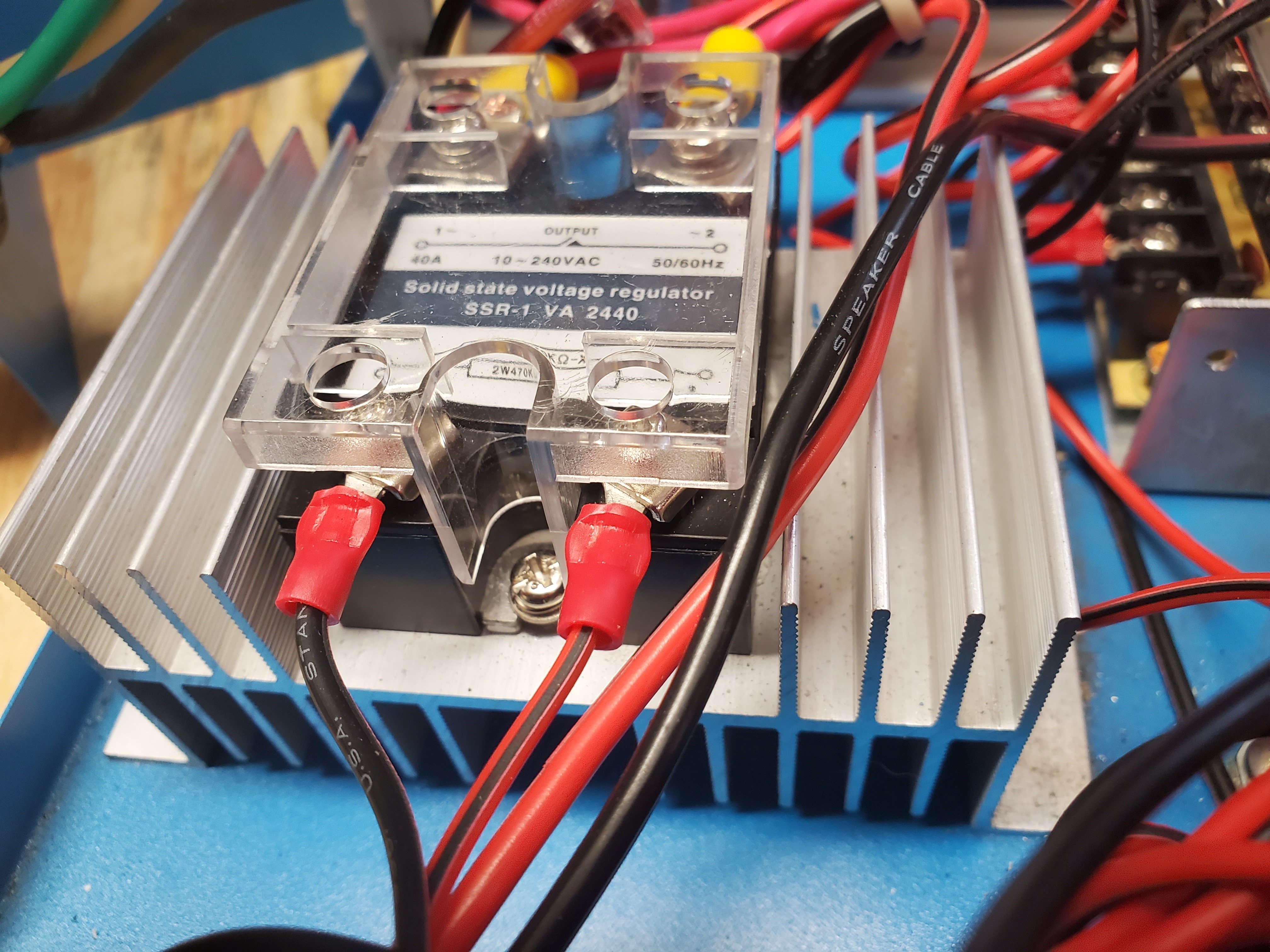
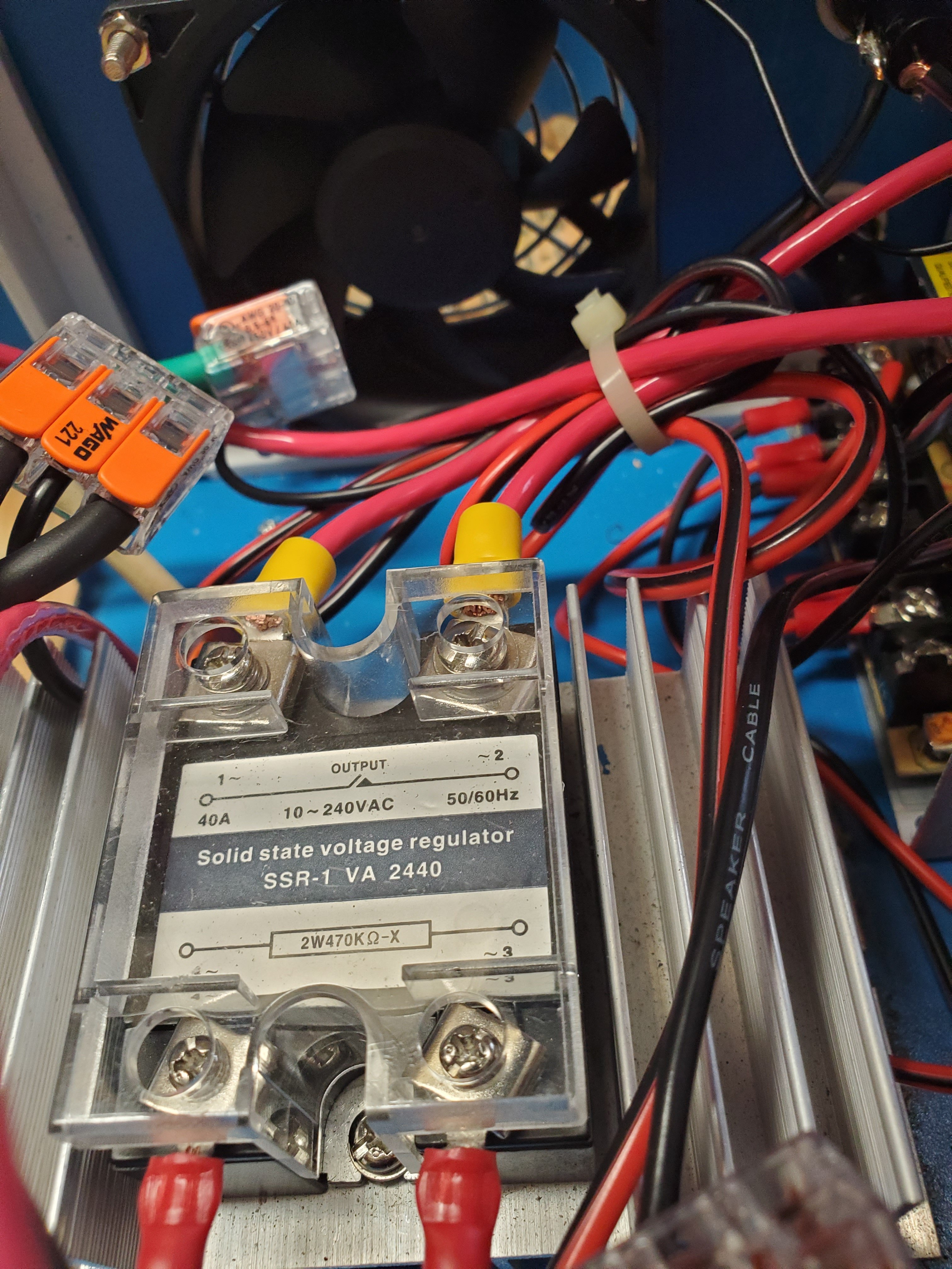
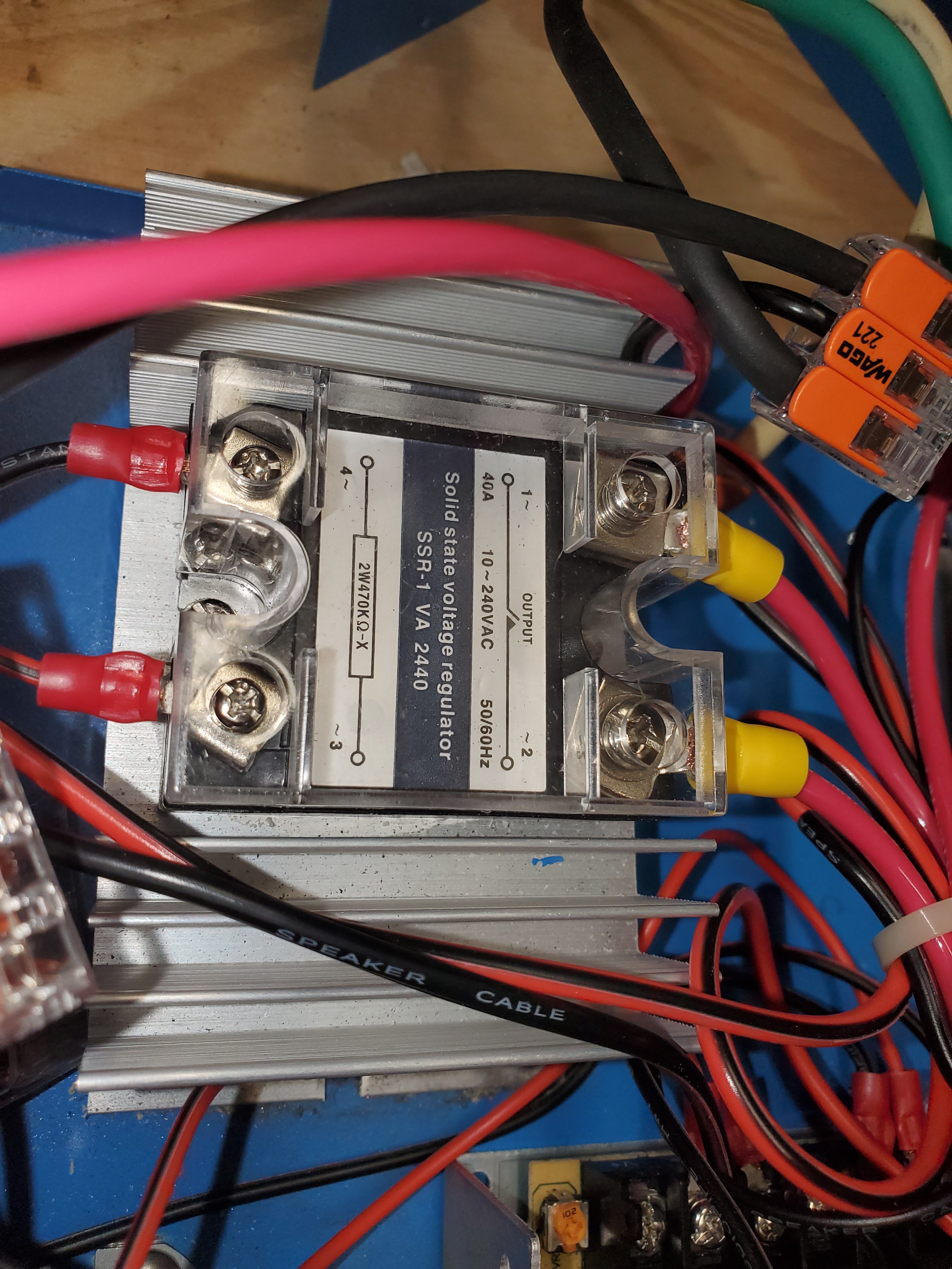
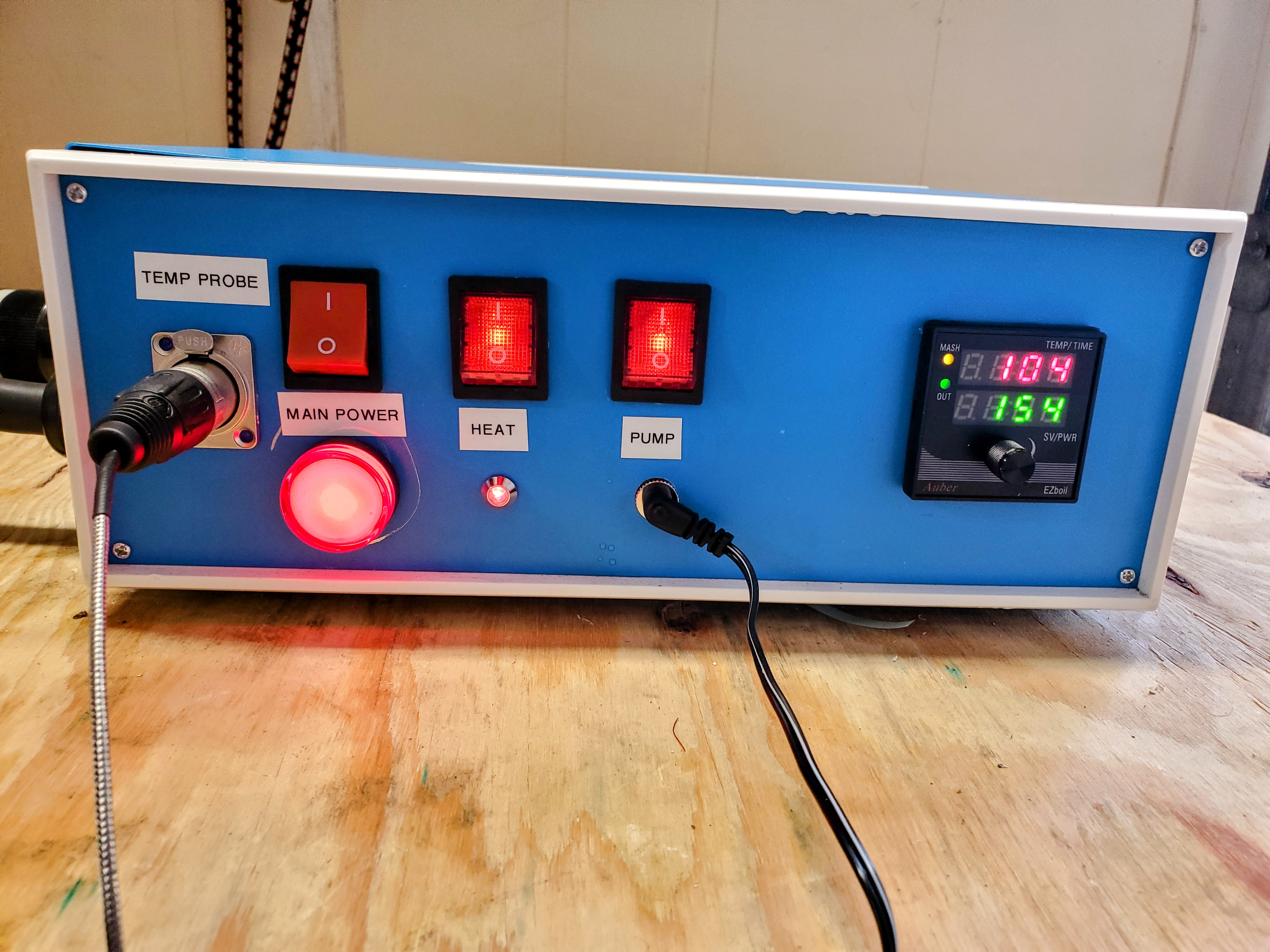
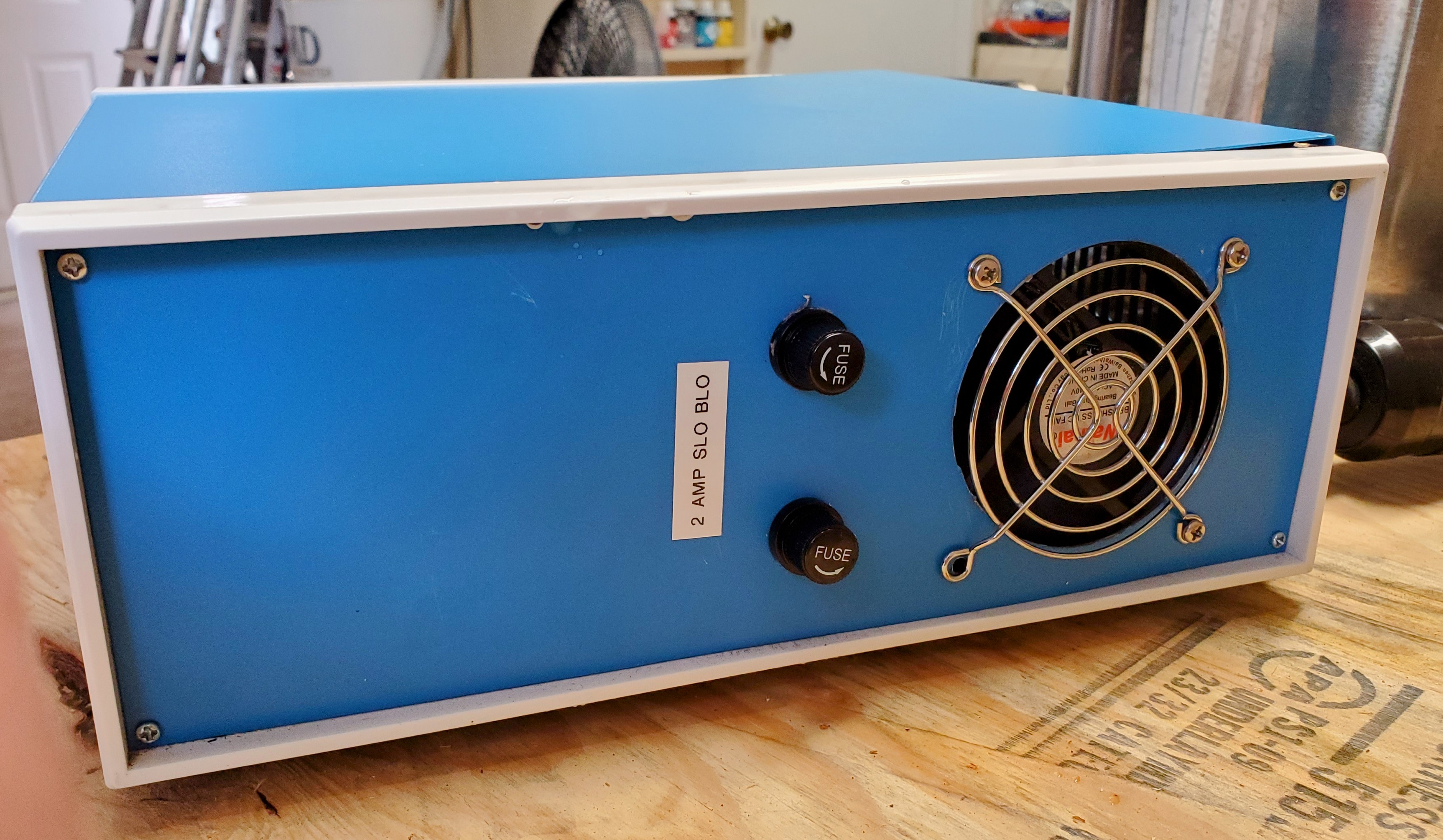
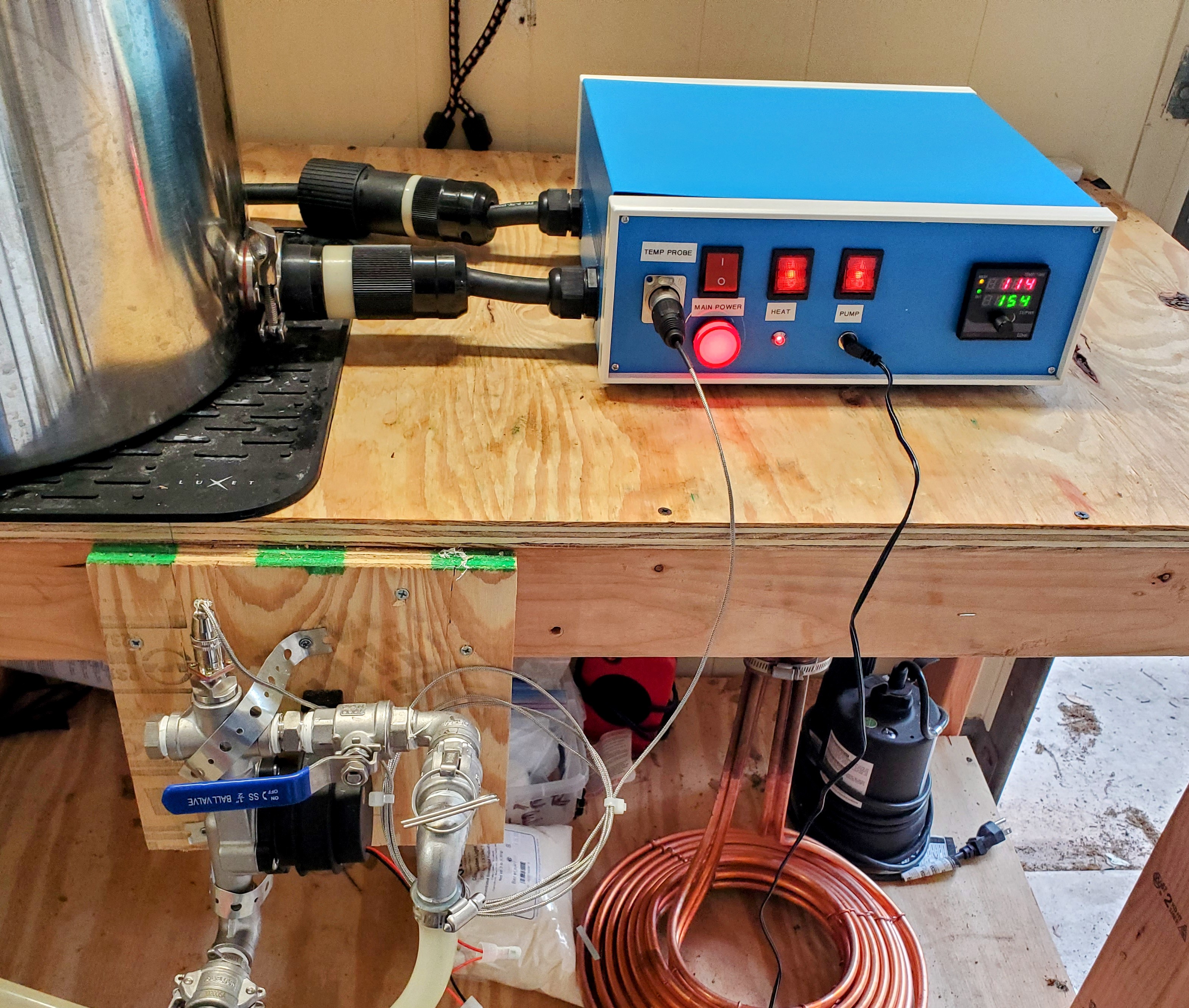
The main power and heating element control, through the DSPR120, are working perfectly. The problem is the pump control. When I connected it per my diagram, I got no power to the pump. I checked the power supply terminals with the multimeter. I got about 120V with each of the power cables connected to the PS, as expected. The ground was connected correctly. However, there was no power across the 24V DC terminals. I then noticed that the red wire from the pump switch was not connected to power. However, when I did connect it, the fuses blew. Why did I have 120V at the red wire terminal on the PS when the red switch wire was not connected to power, and why did it blow the fuses when I did connect it? Also, I assume the PS is bad, since there is no 24V power, correct?

As an option, I'm thinking of eliminating the PS, and going back to a 6-15R. However, the original external PS for that pump only has 2 wires going to the plug. Can I convert this to a 6-15p, and how would I wire that?

Thanks for all your help.
Hops and barley on you tube. He will fix you right up
 
Hops and barley on you tube. He will fix you right up
I've seen (at least some of) his stuff on PID controller design. I wouldn't go to him for design advice, as IMO he doesn't follow best practices for safe designs, nor does he take into consideration possible failure scenarios.

Brew on :mug:
 
I've seen (at least some of) his stuff on PID controller design. I wouldn't go to him for design advice, as IMO he doesn't follow best practices for safe designs, nor does he take into consideration possible failure scenarios.

Brew on :mug:
I made that same conclusion about him myself.

Regardless, I want to show you that you advice was spot on. Everything is working perfectly now! Thank you so much.
 

Attachments

  • 20210510_092929~2.jpg
    20210510_092929~2.jpg
    2.2 MB · Views: 24
  • 20210510_092936~2.jpg
    20210510_092936~2.jpg
    1.3 MB · Views: 21
  • 20210510_092953~2.jpg
    20210510_092953~2.jpg
    1.3 MB · Views: 24
  • 20210510_093036~2.jpg
    20210510_093036~2.jpg
    1.8 MB · Views: 24
What type of 1amp and 10amp inline fuses are suggested?
Something like these?
The automotive fuses that those holders are designed for are only rated to 32V. They might work, but I cannot recommend them. You want fuses and holders rated to 250V minimum.

Brew on :mug:
 
If you are going with a conventional style fuse, use ones rated 250 VAC. What's the difference between a 10 amp 125 VAC fuse and a 10 amp 250 VAC fuse? They will have the same Current vs Time curve. When you put a 125 VAC fuse on a 250 VAC circuit, and the fuse blows, 125 VAC is likely to shatter the glass and create a mess. The 250 VAC fuse will stay in tact.

BTW, There is nothing wrong with putting a 250 VAC fuse in a 125 VAC circuit. It might cost more for the more robust fuse housing. But the safety margin is the same.
 
Pretty sure I use slow blow ceramic fuses. Thought I got all of them at auberins.com but I don't see any 1 amp now looking on my phone. Can't remember what the ezboil or timer required 1 amp or 10amp. I don't have pumps incorporated with my controllers as I use a remote control and run them off an independent gfci outlet.
 

Attachments

  • Screenshot_20210512-171555_Samsung Internet.jpg
    Screenshot_20210512-171555_Samsung Internet.jpg
    326.8 KB · Views: 9
  • Screenshot_20210512-172318_Samsung Internet.jpg
    Screenshot_20210512-172318_Samsung Internet.jpg
    372.1 KB · Views: 9
Pretty sure I use slow blow ceramic fuses. Thought I got all of them at auberins.com but I don't see any 1 amp now looking on my phone. Can't remember what the ezboil or timer required 1 amp or 10amp. I don't have pumps incorporated with my controllers as I use a remote control and run them off an independent gfci outlet.
The EZBoils are listed at "less than 5W" power requirement. 5W @ 120V will draw 5/120 = 0.042A. 1A is enough to drive 24 EZBoils, so 1A fuses are fine on EZBoil, and other PID power supply circuit branches. My designs use 1A fast blow fuses for EZBoil and contractor coil circuit branches. I haven't had any reports of fuses blowing on these designs.

The one instance of a 1A fast blow being inadequate was the design discussed in this thread, where a switching power supply (for a DC pump.) is included. Apparently this power supply has an inrush current (probably due to filter capacitors charging up) significantly higher than the steady state operating current, which is only about 0.6A at 240V. Inrush current is what slow blow fuses are meant to deal with. The fuse blowing problem went away when the 1A fast blow fuses were replaced with 2A slow blow fuses.

I spec 10A fast blow fuses for AC pump supply circuit branches. Chugger type pumps are rated at 1.4A, but motors also often have high inrush currents when started. I haven't heard reports of the 10A fuses blowing in these designs.

It's always ok to use slow blow rather than fast blow fuses, they just cost more.

Fuses should be sized based on the downstream wire gauge. It's the wire sizes that need to be properly chosen for the load currents they are expected to carry (see guidelines here.) You can use larger wire than required by the load, but at some point that just makes your wiring more difficult to do.

Brew on :mug:
 
Last edited:
I think on a utility circuit, going with 10-15 amp @ 120 VAC fuses is fine. Even if all you anticipate is using 1-3 amps as standard draw. I say this because the failure your are protecting against is a short circuit. In which case, the fuse will open just as fast as a fuse close to your expected normal.

Plus changing fuses is a pain. Take reasonable measures to save your pain.
If you use 10A fuses, the down stream wire needs to be 16AWG or larger (lower AWG), for 15A fuses wire needs to be 14AWG or larger. Many loads (PIDs, EZBoils, contactor coils, etc.) don't require much current, and can be wired using finer gauge wire that is easier to work with. If you don't care about ease of wiring, you can use the heavier wire, and higher amp fuses.

Brew on :mug:
 
Back
Top