You are using an out of date browser. It may not display this or other websites correctly.
You should upgrade or use an alternative browser.
You should upgrade or use an alternative browser.
Native ESP8266 BrewPi Firmware - WiFi BrewPi, no Arduino needed!
- Thread starter Thorrak
- Start date

Help Support Homebrew Talk:
This site may earn a commission from merchant affiliate
links, including eBay, Amazon, and others.
Bigdaddyale
Well-Known Member
smaller, cheaper wifi board.What’s that?
stbernts
Well-Known Member
- Joined
- May 20, 2016
- Messages
- 257
- Reaction score
- 43
smaller, cheaper wifi board.
Usage? Is it an alternative to vemos boards?
I think eventually it might be. Right now (according to the google) it has similar capabilities from a hardware perspective, but the software stack is just in the formative stages. Its interface appears to be some strange Lua hybrid.Usage? Is it an alternative to vemos boards?
Basically it’s worth keeping an eye on, as it might be an alternative chipset in the future if they get Arduino library support built out.
steubrew
New Member
- Joined
- Jun 12, 2012
- Messages
- 4
- Reaction score
- 0
@Thorrak Thanks for building this project. I just recently started brewing again and the world of technology has really improved. I recently ordered the STC-1000 in hopes of monitoring my Fermentation, but yesterday came across this project. I started looking for the ESP8266v2 boards, but I cannot locate. Do you happen to have an updated part list posted somewhere where a noob can locate updated parts list and hopefully put together this project. I do already have a rasp pi device.


$7.79 ($7.79 / Count)
Craft A Brew - LalBrew Voss™ - Kveik Ale Yeast - For Craft Lagers - Ingredients for Home Brewing - Beer Making Supplies - (1 Pack)
Craft a Brew


$53.24
1pc Hose Barb/MFL 1.5" Tri Clamp to Ball Lock Post Liquid Gas Homebrew Kegging Fermentation Parts Brewer Hardware SUS304(Liquid Hose Barb)
yunchengshiyanhuqucuichendianzishangwuyouxiangongsi


$53.24
1pc Hose Barb/MFL 1.5" Tri Clamp to Ball Lock Post Liquid Gas Homebrew Kegging Fermentation Parts Brewer Hardware SUS304(Gas MFL)
Guangshui Weilu You Trading Co., Ltd


$33.98
DYKWSWYX Heavy Duty Brewing Gloves (1 Pair) - 55CM Long Chemical Resistant Plastic Gloves for Beer & Wine Making, Cleaning, Homebrew Equipment Protection
wuhanshijiayangzhiyimaoyiyouxiangongsi


$33.99 ($17.00 / Count)
$41.99 ($21.00 / Count)
2 Pack 1 Gallon Large Fermentation Jars with 3 Airlocks and 2 SCREW Lids(100% Airtight Heavy Duty Lid w Silicone) - Wide Mouth Glass Jars w Scale Mark - Pickle Jars for Sauerkraut, Sourdough Starter
Qianfenie Direct


$20.94
$29.99
The Brew Your Own Big Book of Clone Recipes: Featuring 300 Homebrew Recipes from Your Favorite Breweries
Amazon.com


$44.99
$49.95
Craft A Brew - Mead Making Kit – Reusable Make Your Own Mead Kit – Yields 1 Gallon of Mead
Craft a Brew


$176.97
1pc Commercial Keg Manifold 2" Tri Clamp,Ball Lock Tapping Head,Pressure Gauge/Adjustable PRV for Kegging,Fermentation Control
hanhanbaihuoxiaoshoudian


$479.00
$559.00
EdgeStar KC1000SS Craft Brew Kegerator for 1/6 Barrel and Cornelius Kegs
Amazon.com


$58.16
HUIZHUGS Brewing Equipment Keg Ball Lock Faucet 30cm Reinforced Silicone Hose Secondary Fermentation Homebrew Kegging Brewing Equipment
xiangshuizhenzhanglingfengshop

$22.00 ($623.23 / Ounce)
AMZLMPKNTW Ball Lock Sample Faucet 30cm Reinforced Silicone Hose Secondary Fermentation Homebrew Kegging joyful
无为中南商贸有限公司


$49.95 ($0.08 / Fl Oz)
$52.99 ($0.08 / Fl Oz)
Brewer's Best - 1073 - Home Brew Beer Ingredient Kit (5 gallon), (Blueberry Honey Ale) Golden
Amazon.com


$172.35
2 Inch Tri Clamp Keg Manifold With Ball Lock Posts, Pressure Gauge, PRV (0-30 PSI) – Homebrew, Fermentation, Kegging System
wuhanshijiayangzhiyimaoyiyouxiangongsi


$719.00
$799.00
EdgeStar KC2000TWIN Full Size Dual Tap Kegerator & Draft Beer Dispenser - Black
Amazon.com

$76.92 ($2,179.04 / Ounce)
Brewing accessories 1.5" Tri Clamp to Ball Lock Post Liquid Gas Homebrew Kegging Fermentation Parts Brewer Hardware SUS304 Brewing accessories(Gas Hose Barb)
chuhanhandianzishangwu
![Craft A Brew - Safale S-04 Dry Yeast - Fermentis - English Ale Dry Yeast - For English and American Ales and Hard Apple Ciders - Ingredients for Home Brewing - Beer Making Supplies - [1 Pack]](https://m.media-amazon.com/images/I/41fVGNh6JfL._SL500_.jpg)
$6.95 ($17.38 / Ounce)
$7.47 ($18.68 / Ounce)
Craft A Brew - Safale S-04 Dry Yeast - Fermentis - English Ale Dry Yeast - For English and American Ales and Hard Apple Ciders - Ingredients for Home Brewing - Beer Making Supplies - [1 Pack]
Hobby Homebrew

Bigdaddyale
Well-Known Member
There is an excellent thread on how to mod the STC1000 if you have the corrected version of the controller.@Thorrak Thanks for building this project. I just recently started brewing again and the world of technology has really improved. I recently ordered the STC-1000 in hopes of monitoring my Fermentation, but yesterday came across this project. I started looking for the ESP8266v2 boards, but I cannot locate. Do you happen to have an updated part list posted somewhere where a noob can locate updated parts list and hopefully put together this project. I do already have a rasp pi device.
https://www.homebrewtalk.com/forum/threads/stc-1000.464348/
Fermentrack PCB
https://github.com/thorrak/brewpi-esp8266/blob/master/docs/PCB Information.md
This seems to be the newest design: RJ-45 jack and surface mount components.
https://pcbs.io/share/8DDk0
BOM
Bill of Materials:
1x 2-Pin 5mm Pitch Screw Terminal
1x 2-Pin Pin Header
2x 4-Pin Pin Header
5x 10k 0805 Resistor
1x 100uF 1206 Capacitor (Optional)
2x BSS138 MOSFET
1x RJ-11 Jack (RJ-11 variant only)
1x RJ-45 Jack (RJ-45 variant only)
1x WeMos D1 Mini ESP8266 board
1x LCD 20x4 I2C LCD Screen
Last edited:
So been out for a while but back in brewing. Ive used this for some time till I cooked the wemos with the wrong input supply wallwart but still use a couple of wifi brewpi I made many years ago for fridge control because they are still going strong. I was actually using this to control mash temp and just rebuilt it.
The auto update has come a long way. Great job thorrak ! Thanks very much for this.
I followed the auto update and it updated the raspi fine and then I got a fresh wemos d1 mini and plugged it in to flash but my router wouldn't accept it.
I then loaded a simple wifi script with the arduino flasher to the wemos and it recognised the wemos d1 on my router. I then reloaded the fermentrack software through the raspi and it was then recognised the fermentrack and fired up so all good.
Not sure why this was but just reporting what worked for me. I have it merrily ticking over monitoring the garage temp before I use it again.
Seems to be working fine.
Great bit of work and much easier than setting up the brewpi wifi versions
steubrew
New Member
- Joined
- Jun 12, 2012
- Messages
- 4
- Reaction score
- 0
There is an excellent thread on how to mod the STC1000 if you have the corrected version of the controller.
https://www.homebrewtalk.com/forum/threads/stc-1000.464348/
Fermentrack PCB
https://github.com/thorrak/brewpi-esp8266/blob/master/docs/PCB Information.md
This seems to be the newest design: RJ-45 jack and surface mount components.
https://pcbs.io/share/8DDk0
BOM
Bill of Materials:
1x 2-Pin 5mm Pitch Screw Terminal
1x 2-Pin Pin Header
2x 4-Pin Pin Header
5x 10k 0805 Resistor
1x 100uF 1206 Capacitor (Optional)
2x BSS138 MOSFET
1x RJ-11 Jack (RJ-11 variant only)
1x RJ-45 Jack (RJ-45 variant only)
1x WeMos D1 Mini ESP8266 board
1x LCD 20x4 I2C LCD Screen
Thanks for the information, but is there a diagram that I can follow posted some place? I don't have the boards yet but I want to make sure I have the part required.
Bigdaddyale
Well-Known Member
I'm not understanding your question. What board did you order?Thanks for the information, but is there a diagram that I can follow posted some place? I don't have the boards yet but I want to make sure I have the part required.
steubrew
New Member
- Joined
- Jun 12, 2012
- Messages
- 4
- Reaction score
- 0
I am sorry and I am not sure what the heck happened to the rest of the post...I'm not understanding your question. What board did you order?
I have on order the WeMos D1 Mini ESP8266 board, LCD 20x4 I2C LCD Screen and D1 Breakout - LCD SMD Dupont RJ45. I am thinking that a power supply, Do you have a recommendation?
Not having the boards on hand it kind of hard to see the finished product and I was asking if there is a diagram that show all off the boards and connections?
This is what I think the finish product would look like and instead of the Uno board replace with the ESP8266.
https://i.pinimg.com/originals/52/dc/42/52dc42b3d4b4e65689f2ac9e4c1ac44a.gif
I am sorry and I am not sure what the heck happened to the rest of the post...
I have on order the WeMos D1 Mini ESP8266 board, LCD 20x4 I2C LCD Screen and D1 Breakout - LCD SMD Dupont RJ45. I am thinking that a power supply, Do you have a recommendation?
Not having the boards on hand it kind of hard to see the finished product and I was asking if there is a diagram that show all off the boards and connections?
This is what I think the finish product would look like and instead of the Uno board replace with the ESP8266.
https://i.pinimg.com/originals/52/dc/42/52dc42b3d4b4e65689f2ac9e4c1ac44a.gif
I keep meaning to write one, but haven't managed to have a good, rainy weekend day where I've been stuck at home in order to get it done. For now, I'd refer to the two posts I made awhile back which were targeted at a slightly older version of the enclosure. Both are available here:
http://tinybat.ch/
been a while since I accessed the raw data but thought I used to be able to download or access it from Django . can t find it now
I was able to ssh into the raspi via FileZilla and get the full csv.
Is there a spot in Django that I can get to it from there or somewhere else without leaving fermentrack?
Thanks Gerry
I was able to ssh into the raspi via FileZilla and get the full csv.
Is there a spot in Django that I can get to it from there or somewhere else without leaving fermentrack?
Thanks Gerry
been a while since I accessed the raw data but thought I used to be able to download or access it from Django . can t find it now
I was able to ssh into the raspi via FileZilla and get the full csv.
Is there a spot in Django that I can get to it from there or somewhere else without leaving fermentrack?
Thanks Gerry
All of the data is accessible through the web interface (that’s how the graphs work), but I don’t recall if there are visible links to it. If you add an issue to GitHub I can try to find a place to add links - for the currently loaded graphs, if nothing else.
I can get the graphs in the web interface monotone. but it is the total data set in csv I am after as I like to download it and look into it.
I’ll stick one in github. Not really a big issue but if you are in that dove it’s a nice to have. Thanks thorrak
I’ll stick one in github. Not really a big issue but if you are in that dove it’s a nice to have. Thanks thorrak
Does anyone know how to change the colour of the graph lines?
@Thorrak the colours for fridge temp, room temp and fridge setting are all quite similar, can be hard for me to tell them apart some times. Would it be possible to have the 'setting' temps show as dotted or dashed lines, in the same colour as the measured temps? eg a solid and a dashed line in the same colour for fridge measured and fridge setting temp. It would reduce the number of colours shown on the graph.
I'm also interested to work out why sometimes fermentrack keeps such a bang-on temperature (varying by only 0.08 or so degrees C) and other times it's gets itself into a cycling loop of heating and cooling and overshoots by .25 degree either way.
I'm using a regular fridge with a 60w tubular heater and a USB fan. Beer sensor is dipped in the beer, and fridge sensor is hanging in the air at the top of the chamber.
here's my graph showing both flat parts and the overshoot/cycling part on the right hand side
Any ideas?

Zoomed in

@Thorrak the colours for fridge temp, room temp and fridge setting are all quite similar, can be hard for me to tell them apart some times. Would it be possible to have the 'setting' temps show as dotted or dashed lines, in the same colour as the measured temps? eg a solid and a dashed line in the same colour for fridge measured and fridge setting temp. It would reduce the number of colours shown on the graph.
I'm also interested to work out why sometimes fermentrack keeps such a bang-on temperature (varying by only 0.08 or so degrees C) and other times it's gets itself into a cycling loop of heating and cooling and overshoots by .25 degree either way.
I'm using a regular fridge with a 60w tubular heater and a USB fan. Beer sensor is dipped in the beer, and fridge sensor is hanging in the air at the top of the chamber.
here's my graph showing both flat parts and the overshoot/cycling part on the right hand side
Any ideas?
Zoomed in
Yes, thanks for the suggestions! I've added the following issue to GitHub to track the above, and will try to get them implemented shortly: https://github.com/thorrak/fermentrack/issues/306
Thanks
") I got it all set up and controlling my second kit-brew (Tiny Rebel Cwtch) right now. 11 days in so nearly ready for a cold conditioning, via Fermentrack!
I got it all set up and controlling my second kit-brew (Tiny Rebel Cwtch) right now. 11 days in so nearly ready for a cold conditioning, via Fermentrack!Currently trying to get an iSpindel working but it's temperamental sending data to Fermentrack. I can't manage to get back to the iSpindel config AP mode - for some reason the reset button doesn't trigger it, it just reboots and goes back into auto mode. Crazy thing.
Does anyone know how to change the colour of the graph lines?
Click the "Gear" icon in the upper right, then choose "Django Admin". Click into "Config" (under Constance). You can change all the graph colors there.
I'm also interested to work out why sometimes fermentrack keeps such a bang-on temperature (varying by only 0.08 or so degrees C) and other times it's gets itself into a cycling loop of heating and cooling and overshoots by .25 degree either way.
The cycling you're seeing is entirely controlled by the BrewPi controller, and while I've seen reports of similar behavior with legacy controllers the only solution I recall is to reduce the heating power. 60W is a lot of power for most homebrew-sized batches inside a fridge where the heat is well contained. I've seen suggestions for ~20W or less in a lot of cases.
Click the "Gear" icon in the upper right, then choose "Django Admin". Click into "Config" (under Constance). You can change all the graph colors there.
Thanks
Regarding the BrewPi controller, i understand now it's not part of fermentrack. is there another forum where I should be directing those questions to the right people? Ta
this board Description: ESP8266 Breakout Board for BrewPi - Through Hole /w LCD looks like it has to places for relays to be soldered onto th e board. https://pcbs.io/share/46AR1 Can someone confirm this, and if so what is the relay part #?
Thanks
Regarding the BrewPi controller, i understand now it's not part of fermentrack. is there another forum where I should be directing those questions to the right people? Ta
Apologies - I wasn't implying not to ask here, just that you might have more luck asking in the BrewPi thread!
this board Description: ESP8266 Breakout Board for BrewPi - Through Hole /w LCD looks like it has to places for relays to be soldered onto th e board. https://pcbs.io/share/46AR1 Can someone confirm this, and if so what is the relay part #?
It's not a hole for a relay, but a hole for a "SparkFun-style" level shifter board
Bigdaddyale
Well-Known Member
No - The pads are for terminal blocks.this board Description: ESP8266 Breakout Board for BrewPi - Through Hole /w LCD looks like it has to places for relays to be soldered onto th e board. https://pcbs.io/share/46AR1 Can someone confirm this, and if so what is the relay part #?
Does the current version of Fermentrack support a LED screen? or do you have to download additional code/software for this?
Like, an LCD connected to the raspberry pi?
The 20x4 LCD display that connects to the PC breakout board. Using the level shifter.Like, an LCD connected to the raspberry pi?
phreaky
Well-Known Member
Any pointers for setting one up to control glycol cooling? I have seen the github issue relating to glycol and that it is supported, and I've also seen on the original BrewPi that glycol is supported by not having a fridge probe, but with the ESP version if I do not have a fridge probe Fermentrack says it will not be able to control temps. Otherwise I'm not seeing anything directly related to glycol setups. I was able to get it running using only the fridge probe and setting for fridge constant mode, and that seems to function correctly in testing, but then all of the graphs and sensors are labeled as fridge, not beer. Also, I'm guessing that will prevent me from running it on profile mode.
Info on my setup: I have a glycol chiller that will stay at a constant 28 degrees using its own temp controller (although I will probably switch it to an ESP running Brewpi later for web based monitoring). I also run my trunk like using this chiller, so I am not able to let Fermentrack/BrewPi control it's temperature in place of the fridge controls. I currently have one ESP set up with 2 probes and 2 relays, connected to my wifi, and being controlled by my Fermentrack install on a Pi. The plan is to have the ESP control a solenoid valve to run the cooling. Once I have tested enough, I plan on added a second ESP setup for my other fermenter.
Info on my setup: I have a glycol chiller that will stay at a constant 28 degrees using its own temp controller (although I will probably switch it to an ESP running Brewpi later for web based monitoring). I also run my trunk like using this chiller, so I am not able to let Fermentrack/BrewPi control it's temperature in place of the fridge controls. I currently have one ESP set up with 2 probes and 2 relays, connected to my wifi, and being controlled by my Fermentrack install on a Pi. The plan is to have the ESP control a solenoid valve to run the cooling. Once I have tested enough, I plan on added a second ESP setup for my other fermenter.
Bigdaddyale
Well-Known Member
- Joined
- Jul 6, 2013
- Messages
- 142
- Reaction score
- 56
Because this thread has evolved, I am having a hard time figuring out the starting point. I think the Fermentrack is something I will want so I want to start pricing/purchasing parts.
I am finding it difficult to see the links between BrewPi, chipsets, and Fermentrack. Is there a HOWTO that starts with what to purchase, how to wire it, and what to install?
this is a challenge I find with these long involved threads. Topics start, die & merge. info is posted and corrected. Reading through 50+ page is a daunting task.
No complaint about the contributors at all -it's the forum format that challenges me.
Michael Ihle
Member
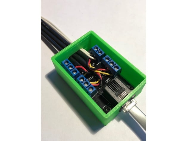
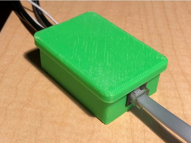
Just thought I would share here that I just made and posted a 3D Print for the sensor breakout board. It worked pretty great. I might glue a couple of thin magnets to the back to enable me to stick it up on the side of my refrig or inside for that matter. Anyway - it was a fun little projet to build.
You can find the Box on Thingiverse here: https://www.thingiverse.com/thing:3184354
Michael
You can find the Box on Thingiverse here: https://www.thingiverse.com/thing:3184354
Michael
Just thought I would share here that I just made and posted a 3D Print for the sensor breakout board. It worked pretty great. I might glue a couple of thin magnets to the back to enable me to stick it up on the side of my refrig or inside for that matter. Anyway - it was a fun little projet to build.
You can find the Box on Thingiverse here: https://www.thingiverse.com/thing:3184354
Michael
This thing is awesome. I also hadn't thought about facing the screw terminals inwards - the way I've always been using them was facing outwards, which I think is part of why I've had so much trouble getting the wires to remain secured.
Thanks for designing this - and further thanks for posting everything on Thingiverse for others to print/use!
Just dipping my toes into the waters here when I found myself in the dark, literally!
What is the expected behavior of the ESP8266 runnning brewpi following a whole home power outtage?
In my situation, when power returned, the ESP8266 came up before my router was back online.
It appears that the ESP8266 (failing to get a dhcp address from the router) went into Soft-AP mode and was then unreachable by Fermentrack. I had to power-cycle ESP8266 so it would get its static DHCP address before Fermentrack would see it again.
- Is this the expected behavior?
- Is the ESP8266 data intended for Fermentrack queued up until connection is restored or is the data lost since Fermentrack couldn't 'see' the ESP8266 due to the WiFi mix up?
Just dipping my toes into the waters here when I found myself in the dark, literally!
What is the expected behavior of the ESP8266 runnning brewpi following a whole home power outtage?
In my situation, when power returned, the ESP8266 came up before my router was back online.
Sorry for the delay in responding!
What you are describing is currently the expected behavior, though admittedly it may not be the desired behavior.
After a power outage, the ESP8266 controller will restart, and then search for the configured WiFi network. If the network is unavailable (such as if the router hasn't finished rebooting) then - as you noted - it will go into Soft AP mode thinking that the network it needs to connect to no longer exists. After ~5 minutes or so, it will give up on this, and just go into "offline" mode. (As a side note, if anyone doesn't think this is the right approach, I've added an issue on GitHub for discussion - happy to consider alternatives if there's enough interest)
While in "offline" mode, the controller will maintain whatever the last temperature setpoint (either beer or fridge) it knew, indefinitely. For beer profiles this gets a bit strange, as the profile is maintained on the Raspberry Pi - not on the controller itself. This means that if you were 3/4 of the way done with a ramp from 70 to 60 degrees, for example (so your controller had just been told to maintain temp at 62.5 degrees), your controller would maintain whatever that last "setpoint" was (so in this example - 62.5 degrees) until it reestablished connection with the Pi. Because profiles are time-based, if it finally reestablished connection after the ramp was originally scheduled to complete then it would "jump" from that setpoint (62.5 deg) to wherever it would have been had the connection not been lost (60 degrees).
Unfortunately, the firmware does not have the ability to "queue" missing readings and the like, so any data points generated while the controller isn't connected to the script are lost and unrecoverable.
I keep meaning to write one, but haven't managed to have a good, rainy weekend day where I've been stuck at home in order to get it done. For now, I'd refer to the two posts I made awhile back which were targeted at a slightly older version of the enclosure. Both are available here:
http://tinybat.ch/
I too would be interested in a more updated wiring diagram. I see the potential of what this can do (I am currently using it to monitor my STC controlled temps). But I'm not quite sure how to bridge the gap between wiring of the STC to the esp.
I am using a modified version of this case which is essentially just the STC switching an outlet. I would love to continue with the wall outlet approach using Fermentrack. I imagine a relay would handle the heavy lifting based on the heat/cool pins of the esp. Definitely could use some more example material to work with.
Also, is it possible to get a url for the graph? I'd like to embed it on a smart home web server. Your graph seems to be truly embedded with the fermentrack page without any options to reference it.
Thanks for the help. I hope I can continue forward with this product!
I too would be interested in a more updated wiring diagram. I see the potential of what this can do (I am currently using it to monitor my STC controlled temps). But I'm not quite sure how to bridge the gap between wiring of the STC to the esp.
I am using a modified version of this case which is essentially just the STC switching an outlet. I would love to continue with the wall outlet approach using Fermentrack. I imagine a relay would handle the heavy lifting based on the heat/cool pins of the esp. Definitely could use some more example material to work with.
In this build, the STC would be completely removed. The ESP8266 would control a relay, which itself would then control an outlet.
, is it possible to get a url for the graph? I'd like to embed it on a smart home web server. Your graph seems to be truly embedded with the fermentrack page without any options to reference it.
It's not that straightforward, unfortunately -- the graph itself is generated dynamically using JavaScript (dygraphs) rather than being an image that could be linked in. The divs that contain the graphs are here in the template, while the javascript that actually generates the graph is in this block. This line is the most important, as it's how the data actually gets loaded (it's where the data file is specified).
The only bit of this that would be hard to replicate is that line (the CSV link) as it's defined at runtime, and will change as you stop/start logging. If this trips you up, I wouldn't object to exposing the CSV/JSON URLs via some form of API, but you would then need to figure out how to integrate that into your implementation.
I really appreciate the detailed response. I definitely understand that I'm jumping in with some pretty basic questions. I'll take a look at what you provided but I think the API might be the best answer as I'm sure others might be interested in the same.
I use something called ActionTiles where I was hoping to embed my fermentation graph as one of the tiles. Up to this point I've only embedded images and gifs into it but hopefully I can proceed forward with the API (along with the help of a friend).
In terms of the wiring, I have two STC-1000s. One controls my DIY glycol cooling while the other controls heating/cooling. Seems pretty obvious, but my best bet would be to wire up two esp8266/relays and have the glycol act as a "beer" with only a cooling pin? Or do you have other glycol support that I have missed.
Thanks again
Hey Thorrak,
I added the iSpindel I built as a gravity device -- it was super simple to setup and the calibration tool was great too (thanks!). I brewed yesterday and I'm using the iSpindel for the first time.
I have a quick question about the way gravity is displayed on the graphs on the dashboard. For the dashboard for my fermentation controller (I use a brewpi), the gravity is being displayed as "steps." On the iSpindel dashboard page, the graph is much smoother and looks like points are getting logged every 900 seconds (15 min). Is this the normal behavior? (Here are screenshots) Thanks!
Brewpi dashboard:

iSpindel dashboard:

I added the iSpindel I built as a gravity device -- it was super simple to setup and the calibration tool was great too (thanks!). I brewed yesterday and I'm using the iSpindel for the first time.
I have a quick question about the way gravity is displayed on the graphs on the dashboard. For the dashboard for my fermentation controller (I use a brewpi), the gravity is being displayed as "steps." On the iSpindel dashboard page, the graph is much smoother and looks like points are getting logged every 900 seconds (15 min). Is this the normal behavior? (Here are screenshots) Thanks!
Brewpi dashboard:
iSpindel dashboard:
Hey Thorrak,
I added the iSpindel I built as a gravity device -- it was super simple to setup and the calibration tool was great too (thanks!). I brewed yesterday and I'm using the iSpindel for the first time.
I have a quick question about the way gravity is displayed on the graphs on the dashboard. For the dashboard for my fermentation controller (I use a brewpi), the gravity is being displayed as "steps." On the iSpindel dashboard page, the graph is much smoother and looks like points are getting logged every 900 seconds (15 min). Is this the normal behavior? (Here are screenshots) Thanks!
Brewpi dashboard:
View attachment 597407
iSpindel dashboard:
View attachment 597408
Yes, that's normal. Due to the way that the data is stored, there's a single data set for each logged "beer" where each row contains each of the data points. What this means is that whereas you have a single data point per reading in the iSpindel graph (so one every 900 seconds) - in the BrewPi Device graph, you have that same data point copied every time the BrewPi controller records a measurement (so probably every ~15 seconds or so).
There might be a better way of combining the data sets given that the X axes are the same, but unfortunately I'm not all that good with dygraphs. As an alternative, if you have other charting software that you prefer, you could combine the data sets manually as they're both saved out independently as well when each beer is logged.
I finally received all my components and break out board https://pcbs.io/share/46AR1 I ordered the wrong phone jack connector to attach to the 6 hole place. Can I just solder 3 wires to certain holes to get + - and the one wire signal? if so, which ones do I solder to?
... Row 1 LMR left, middle, right
... Row 2 LMR
The holes are lined up like the periods I posted above. It appear from the traces on the board, that Row 1 middle goes to D6 for the one wire signal. Row 2 Middle traces back to ground, Which one is power for the temp sensors and what are the other 3 for?
It appears that no traces go to R1 Left and Row2 right.
What do I do with the Jumper, does it need to be connected or is it optional?
Similar threads
- Replies
- 10
- Views
- 2K
- Replies
- 3
- Views
- 2K
- Replies
- 7
- Views
- 2K
