Native ESP8266 BrewPi Firmware - WiFi BrewPi, no Arduino needed!

Homebrew Talk - Beer, Wine, Mead, & Cider Brewing Discussion Forum

Help Support Homebrew Talk - Beer, Wine, Mead, & Cider Brewing Discussion Forum:

This site may earn a commission from merchant affiliate links, including eBay, Amazon, and others.
Updated, all looking good my end. A minor bug, which I didn't notice before, when I try and zoom in by time (left or right) on the graph the data dissappears. Zooming in by temp (up and down) works OK. I'm 12 hours into a beer profile BTW.

Thanks for catching this - the timezone changes I made to the graph display apparently caused an issue. All fixed now. Sorry about that!


So something's up with my version of Fermentrack, (or possibly the RPI) a few days ago I logged on and had the cannot receive LCD, so I updated (as there was one available and it kicked it back into life same profile etc.

Logged in again this morning and again it said it couldn't receive LCD so I rebooted and it seemed like the Fermentrack must have shut down completely as the beer had dropped to my ambient cellar temp and when I rebooted it wasn't running the beer profile.

I've started it up again and will check in on it daily but could it be an ESP issue?

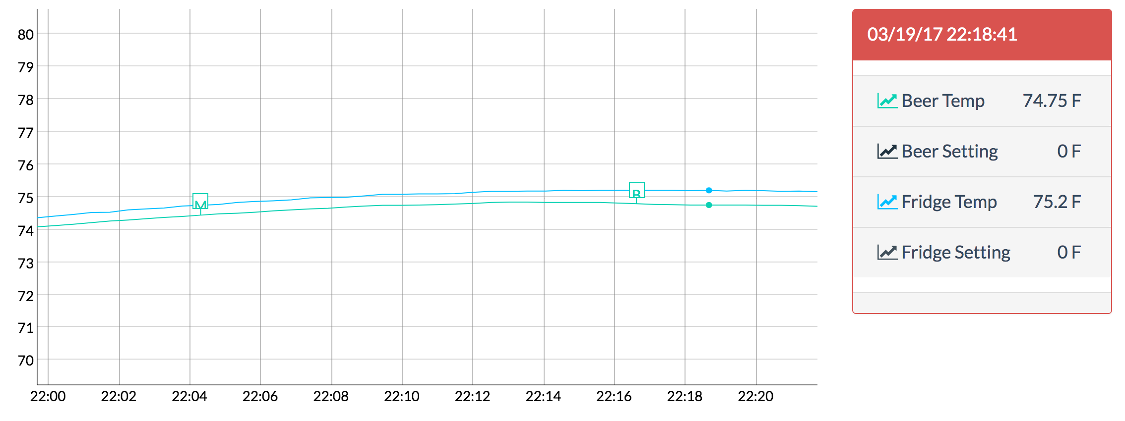
View attachment 406126

Do you have an LCD attached to the ESP? If so, do you happen to recall what that LCD read? Also, do you happen to have a door sensor attached to the ESP?

If your beer switched back to cellar temperature, that would point to an issue with the controller.
 
No no LCD attached or door sensor, and it's worked fine up until this batch.. I think if it drops out again, I'll go and check to see if there is any power going to the ESP.

I don't think it switched to cellar temp I think it just switched off.
 
Thanks for catching this - the timezone changes I made to the graph display apparently caused an issue. All fixed now. Sorry about that!

Updated and all working. I'll leave you alone now ;)
The Kolsch is chugging away nicely at 15c, I'm obsessively checking the chart! This thing just amazes me, sooooo much better than my STC build :rockin:
 
@Thorrak, sorry if this has been discussed previously. Next to the temperatures (to the right of the chart) is there any reason why you decided to omit the coloured legend, which is included in Brew Pi (little coloured circles)?
 
Hi all.

In case anyone is interested, I've just published this remix of thorrak's original enclosure for EUstyle sockets
https://www.thingiverse.com/thing:2416425

regs,
peram

That's awesome! What plugs does that one use? EU-style panel mount?

@Thorrak, sorry if this has been discussed previously. Next to the temperatures (to the right of the chart) is there any reason why you decided to omit the coloured legend, which is included in Brew Pi (little coloured circles)?

Probably, but I can't remember what it was!

I've added an issue to GitHub to track this.

Also, I'm not sure how well the line graph colors work for people with color blindness or displays that don't retain color fidelity well. To help with this, we should also probably make it so the colors are user-configurable. Issue for that is here.
 
Awesome, just... awesome! :mug:

I revisited the BrewPi charts and the 'dots' in the legend can be toggled to show/hide data on the chart. Not a feature I used but mentioned it for completeness.

As a side note, 4 days into a profile and no screen scramble with mechanical relays lol
 
Another day, another update - this time to fermentrack-tools.

Over the past few months, I've had a handful of people ask whether or not Fermentrack can be installed alongside Raspberry Pints. Although I don't have a RaspberryPints installation available to test with, from my research it should be a pretty simple thing to do. In an attempt to support this, I've pushed a script to fermentrack-tools which will add PHP support to Nginx and tell Nginx to serve all the files Apache did previously.

Note - Support for this is optional, and is not installed by default.

I'm in the midst of building a Raspberry Pints system so I tested this legacy-support install. The initial installation failed with an nginx configuration error. Unfortunately I don't have the log but I rebooted the Pi and re-ran the installation script and everything completed successfully.

Anyway, everything looks good, and both Fermentrack and Raspberry Pints pages are being served from the same Pi without any problems. Unfortunately I don't have the rest of the hardware so I can't get much past the initial configuration pages, but I'm going to move ahead with this setup once I do. I'll report back with progress.
 
Been having a nightmare lately trying to get the Pi Zero W to keep its WiFi up. A lot of searches suggested turning off the WiFi power management but that did not help. I came across a few scripts that were all similar and reported that they fixed the problem, I can confirm the script works brilliantly. I followed this guide to resetting the WiFi if it goes down: http://weworkweplay.com/play/rebooting-the-raspberry-pi-when-it-loses-wireless-connection-wifi/

You can test that you did everything correctly by issuing the command to take down the WiFI:

Code:
sudo ifdown --force wlan0

Then wait 5 minutes, the cron will run and bring the WiFi back up.

For anyone having similar issues give this a go. ;)
 
Cleaning house. I have Three boards available. Five dollars each including shipping.I can solder on SMD for a dollar more. Send an email to jamesw@ tstonramp dot com, be sure to include
" ESP8266 BrewPi " in the subject
attachment.php
 
I'm still missing the probe connector but I've got everything together and can't get the LCD working. I've taken a meter to the connections and I'm getting about 4.7 volts to the LCD and the correct pins from the ESP are connecting to SCA and SCL.

Any ideas?

Here's what it looks like:

espLCD.jpg
 
I'm still missing the probe connector but I've got everything together and can't get the LCD working. I've taken a meter to the connections and I'm getting about 4.7 volts to the LCD and the correct pins from the ESP are connecting to SCA and SCL.

Any ideas?

Here's what it looks like:
Keep turning the screw on the pot.I had the same problem. It took 20 revolutions before the data would appear. You might have to bump up the voltage to 9v
 
I'm still missing the probe connector but I've got everything together and can't get the LCD working. I've taken a meter to the connections and I'm getting about 4.7 volts to the LCD and the correct pins from the ESP are connecting to SCA and SCL.

Any ideas?

Here's what it looks like:

I'd start by doing what @bigdaddyale suggested and try turning the potentiometer on the back of the LCD "backpack" first - that's the simplest solution, and might be causing your issue.

If that doesn't help - I can't see the logic level converter, but I would check that it's oriented correctly. Rows 1 & 3 of the LCD being boxes indicates that it's not being initialized by the firmware, which would in turn indicate that the SCL/SCA data isn't making it to the LCD.

It would make sense to also check all the connections between the ESP8266 and the SCL/SCA lines on the LCD, so D1/D2 to the logic level converter, then the logic level converter to the screw terminals, then the screw terminals to the wires, and last the wires to the backpack on the LCD.

Last, I'm assuming this is done but if you haven't flashed your ESP8266 already, you should go ahead and do so. There isnt' default firmware on the ESP8266 that will initialize/output data to the LCD.

First, thanks to you and @bigdaddyale for the help.

The pot on my LCD only turns about one revolution total. One way it was blank and the other way rows 1 and 3 were full bright.

As for the logic level converter, I'm pretty sure it's correct. Here's a close-up.

brewpi-68217.jpg


I took a meter to all of the connections you mentioned and they all check out good. As for the firmware, I flashed it with the nodemcu flasher and the script shows as running from Fermentrack.

I've got two of the same displays and both are doing the same thing. I think there was another image of an LCD from WAY back in this thread that looked the same but if I recall it was an address issue that was subsequently fixed. Anyway, I'm still at a loss. It's not a big deal because I don't have a problem running it headless, but it would be cool to get it working.
 
First, thanks to you and @bigdaddyale for the help.

The pot on my LCD only turns about one revolution total. One way it was blank and the other way rows 1 and 3 were full bright.

As for the logic level converter, I'm pretty sure it's correct. Here's a close-up.

brewpi-68217.html


I took a meter to all of the connections you mentioned and they all check out good. As for the firmware, I flashed it with the nodemcu flasher and the script shows as running from Fermentrack.

I've got two of the same displays and both are doing the same thing. I think there was another image of an LCD from WAY back in this thread that looked the same but if I recall it was an address issue that was subsequently fixed. Anyway, I'm still at a loss. It's not a big deal because I don't have a problem running it headless, but it would be cool to get it working.

Doh. I couldn't get the pic to load on my phone, but if it's in the right way I'm not sure what the issue would be. I think @Mikmonken has the same PCB in active use - but I'm not sure if he uses LCDs with it or runs it headless. He sent me one of the ones he had fabricated awhile back, but I haven't had a chance to solder it up myself just yet unfortunately.

On the address point - that's actually a good catch. The firmware now should auto-detect I2C addresses though, so this shouldn't be an issue any longer.

The only other easy thing I can think to try is just switching the SCL and SCA lines (even though they're connected correctly at the moment). I don't think this will hurt anything in this case, but it's possible that either the LCD backpack labeling (or my PCB design!) could be flipped.

It's definitely not the address because I hooked up an Arduino and got it working with 0x3F. I'll keep messing around with it and since I've got the parts I'll probably build up another board too to see if it makes a difference.
 
It's definitely not the address because I hooked up an Arduino and got it working with 0x3F. I'll keep messing around with it and since I've got the parts I'll probably build up another board too to see if it makes a difference.
I would bump up the power to 9v and see what happens. You're running the whole board off USB power, I don't think that is enough. Cut the ends off a wall wort and insert into the 5+ terminal and you should be good.


PS don't forget to unplug the USB from the D1 Mini before you run power to the board.
 
Doh. I couldn't get the pic to load on my phone, but if it's in the right way I'm not sure what the issue would be. I think @Mikmonken has the same PCB in active use - but I'm not sure if he uses LCDs with it or runs it headless. He sent me one of the ones he had fabricated awhile back, but I haven't had a chance to solder it up myself just yet unfortunately.

On the address point - that's actually a good catch. The firmware now should auto-detect I2C addresses though, so this shouldn't be an issue any longer.

The only other easy thing I can think to try is just switching the SCL and SCA lines (even though they're connected correctly at the moment). I don't think this will hurt anything in this case, but it's possible that either the LCD backpack labeling (or my PCB design!) could be flipped.

I'll have to check which one I am using with my Sousvide as that seems to work fine with the LCD attached to it, but Im not sure which board that is using.
 
I would bump up the power to 9v and see what happens. You're running the whole board off USB power, I don't think that is enough. Cut the ends off a wall wort and insert into the 5+ terminal and you should be good.


PS don't forget to unplug the USB from the D1 Mini before you run power to the board.

I measured the voltage again last night at the LCD and it's getting 4.9V. I'll try and dig up a 9V supply tonight and give it a try but I'm leaning toward some other hardware being wrong though, because the LCD worked when hooked to an Arduino via USB. Who knows, it could be the Wemos or the logic level converter.
 
I connected directly without level converter.
I also tried supplying 3.3v and 5v to I2C LCD. They all work.
I don't recommend, though.
 
Good news! I went back through with a meter and it turns out it was a bad solder connection on one of the ground pins for the level converter. When I was probing it earlier I must have been touching the pad and not the pin and when I went back to test the pins there was no connection. Re-soldered it and the LCD is working great now.

Thanks for the troubleshooting.
 
was having trouble with the install but realized it was mainly because i had come back to it after a while and it doesn't like loading over the top of one of the first version brewpi installs.
I reformatted and loaded Jessie again and then used the auto load script. Tales time but very easy and after resetting eeprom I now have it ticking away again nicely. Very slick looking interface. I went with the raspi model b sitting on top of my router with a LAN cable to it and the house wifi connected to the ESP board. LCD also running fine.:D
Thanks Thorrak. Ill give it a day to make sure its all ok thenuse it to control a fridge.
great job :mug:

Thanks! If there was anything throughout the setup process that was confusing or incorrectly documented, please let me know. In addition to the additional graph features my focus at the moment is documentation. Then, official release!
 
Fermentrak seems very intuitive and easy to use.
That Django administration is pretty cool.

I found the csv download as well as i use this in brewpi to play with the data. i noticed the log time has a "Z" on the end of the time. Little bug?

log_time beer_temp beer_set beer_ann fridge_temp fridge_set fridge_ann room_temp state temp_format associated_beer_id
2017/07/20 10:05:13Z 20.56 0 20.94 0 20.75 0 C 1
2017/07/20 10:05:44Z 20.59 0 20.98 0 20.75 0 C 1
 
Working on the first part of configurable colors/color display:

5LehHir.png


...unfortunately, the default palette I've chosen is pretty hideous (Look at the icons to the left of the legend). If anyone has suggestions, please let me know -- at this point it's not too late to save everyones' eyes!

Next up is making the graph lines toggleable by clicking on the icon. Once that's done I'll merge everything back into master to release it.
 
PS. after that don't forget the LCD re-initialise ;) Then we have perfection!

Soon-ish! That needs to be done in the firmware. My plan at the moment is to shift back to the firmware for a few weeks after I get the first "official" Fermentrack release out.

In addition to the LCD reset I'd like to officially get the code base brought up to be based on 0.2.10 (or whatever the last Arduino release was) rather than 0.2.4. Not sure what changes there are (if any) but I don't like the divergence. Beyond that, the (legacy) firmware is pretty much complete in my mind. I'll come back and add stuff if people have suggestions, but otherwise there's not much else to add I don't think.
 
Back
Top