Native ESP8266 BrewPi Firmware - WiFi BrewPi, no Arduino needed!

Homebrew Talk - Beer, Wine, Mead, & Cider Brewing Discussion Forum

Help Support Homebrew Talk - Beer, Wine, Mead, & Cider Brewing Discussion Forum:

This site may earn a commission from merchant affiliate links, including eBay, Amazon, and others.
Well there goes my idea. Let me see what I can do when I get home.

Out of curiosity what demo code did you use which worked?

The example code that came with the OneWire library called DS18x20_Temperature.

I took a look at that code, and don't see any particular reason it would work and the code included with the firmware wouldn't. I'll shoot you a PM with some potential steps to diagnose the issue.
 
Hi,
Did a fresh install last night. Pi and vmos is running like it should as far as I can tell.
So - On to the wiring.

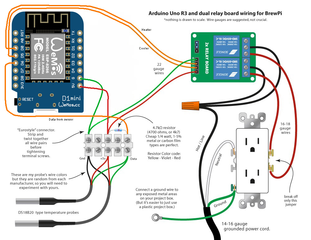
Will this work well? I have no plan for LCD at the moment. :ban::mug:

Edit reson:
Wiring updated to correct PIN usage.

BrewPi_Vmos_d1_Multiple_Fermentor_howto.jpg
 
Hi,
Did a fresh install last night. Pi and vmos is running like it should as far as I can tell.
So - On to the wiring.

Will this work well? I have no plan for LCD at the moment. :ban::mug:
Nice, and nice diagram! I think you may have the old version of the pinout as I see heat/cool on D3/D4. The latest version is the following:

D0 - Heat
D1 - I2C SCL
D2 - I2C SDA
D3 - Buzzer (currently unsupported)
D4 - N/C
D5 - Cool
D6 - OneWire Data
D7 - Door (Untested)
 
Nice, and nice diagram! I think you may have the old version of the pinout as I see heat/cool on D3/D4. The latest version is the following:

D0 - Heat
D1 - I2C SCL
D2 - I2C SDA
D3 - Buzzer (currently unsupported)
D4 - N/C
D5 - Cool
D6 - OneWire Data
D7 - Door (Untested)

Thanks, will update, and upload new Diagram - which by the way is something I have copied from the "make brewpi for cheap" thread, and modified. Hope nobody is going to hate me for dooing that.

PS. Perhaps the post on the first page should be updated with the right pinout description. I did everything step by step from that post.

I'd love to update it -- but it won't let me. :(

The original post is too old, I think. I need to see if I can ping an admin or someone to get some help in that sense.
 
Sure thing. First - a warning to all who may come along and see this - Do not print this! It is a work in progress, and is based on an earlier enclosure design. I can't guarantee anything will actually fit inside -- or even that the lid will fit on the enclosure.

That said, the files are located on Thingiverse. The idea is that the LCD mounts in the lid to the enclosure, with the other stuff inside. This is a pic of last weekend's failed print with the boards overlaid on top:

50ec63b16cf8cfd0cbc1a186a9e6eb2e_preview_featured.jpg


A 5V power supply is on the left, the relay in the center, and my SMD PCB on the right. The idea is that you use snap in power jacks (I haven't shopped those - you can get them way cheaper than that link) in the front of the box, and IEC-320 (again - haven't shopped) for AC in. You can see what I'm talking about in the rendering on Thingiverse.

As an alternative, you could replace the panel mount power jacks with a standard outlet - I haven't thought too much about this, but it might be easier.

Link to the PSU?
 
Link to the PSU?

@Thorrak - what power supply did you end up using for this? If I am going to use your design for the box (no reason not to) I should make sure I have the same one.

Here's the PSU that I used -- but I will mention that I haven't yet actually powered this thing up.

I finally finished printing the case (and the lid) on Monday, but I've been busy at work and haven't had a chance yet to assemble the case. That's become this weekend's project -- I'll report back with photos.

If you bought the wrong PSU, you are going to have company. I bought a couple. :)

Can't wait to see some pics of the completed case.
 
If you bought the wrong PSU, you are going to have company. I bought a couple. :)

Can't wait to see some pics of the completed case.

Hah! Still assembling everything, but I just tested the PSU and it puts out 4.99v according to my multimeter. I'll report back once everything else is wired up.

Also, I just realized that I need some kind of utility script to actually test that everything is assembled correctly. (Test the LCD, test the relays) I'll get that thrown together this afternoon & add it to the repo.
 
So my device is in that weird state where it will not pull up the device configuration page. I get that spinning flower thingie but nothing ever loads despite how long it sits. I can open this up for you if you want to look ... or I can just reset everything and it will work again.
 
So my device is in that weird state where it will not pull up the device configuration page. I get that spinning flower thingie but nothing ever loads despite how long it sits. I can open this up for you if you want to look ... or I can just reset everything and it will work again.
Seems like the script was locked up. I had the script running and I flashed the D1. When I tried to configure it was in that state. Resetting the D1 did noting. I killed the script and allowed it to restart and it took off.

Here's the stderr.txt from this morning:

Code:
 Nov 12 2016 00:00:00   Notification: New day, creating new JSON file.
 Nov 12 2016 09:55:23   Opening serial port
 Nov 12 2016 09:55:34   No serial attached BrewPi found.  Trying TCP serial (WiFi)
 Nov 12 2016 09:55:34   Connecting to BrewPi brewpiesp.local on port 23
Traceback (most recent call last):
  File "/home/brewpi/brewpi.py", line 333, in <module>
    ser = util.setupSerial(config, time_out=0)
  File "/home/brewpi/BrewPiUtil.py", line 160, in setupSerial
    ser = tcpSerial.TCPSerial(config['wifiHost'],int(config['wifiPort']))                    
  File "/home/brewpi/tcpSerial.py", line 19, in __init__
    self.sock.connect((host, port))
  File "/usr/lib/python2.7/socket.py", line 224, in meth
    return getattr(self._sock,name)(*args)
socket.gaierror: [Errno -2] Name or service not known
 Nov 12 2016 09:56:02   Opening serial port
 Nov 12 2016 09:56:12   No serial attached BrewPi found.  Trying TCP serial (WiFi)
 Nov 12 2016 09:56:12   Connecting to BrewPi brewpiesp.local on port 23
Traceback (most recent call last):
  File "/home/brewpi/brewpi.py", line 333, in <module>
    ser = util.setupSerial(config, time_out=0)
  File "/home/brewpi/BrewPiUtil.py", line 160, in setupSerial
    ser = tcpSerial.TCPSerial(config['wifiHost'],int(config['wifiPort']))                    
  File "/home/brewpi/tcpSerial.py", line 19, in __init__
    self.sock.connect((host, port))
  File "/usr/lib/python2.7/socket.py", line 224, in meth
    return getattr(self._sock,name)(*args)
socket.gaierror: [Errno -2] Name or service not known
 Nov 12 2016 09:57:02   Opening serial port
 Nov 12 2016 09:57:12   No serial attached BrewPi found.  Trying TCP serial (WiFi)
 Nov 12 2016 09:57:12   Connecting to BrewPi brewpiesp.local on port 23
Traceback (most recent call last):
  File "/home/brewpi/brewpi.py", line 333, in <module>
    ser = util.setupSerial(config, time_out=0)
  File "/home/brewpi/BrewPiUtil.py", line 160, in setupSerial
    ser = tcpSerial.TCPSerial(config['wifiHost'],int(config['wifiPort']))                    
  File "/home/brewpi/tcpSerial.py", line 19, in __init__
    self.sock.connect((host, port))
  File "/usr/lib/python2.7/socket.py", line 224, in meth
    return getattr(self._sock,name)(*args)
socket.gaierror: [Errno -2] Name or service not known
 Nov 12 2016 09:58:02   Opening serial port
 Nov 12 2016 09:58:13   No serial attached BrewPi found.  Trying TCP serial (WiFi)
 Nov 12 2016 09:58:13   Connecting to BrewPi brewpiesphigh.local on port 23
 Nov 12 2016 09:58:13   Notification: Script started for beer 'My First BrewPi Run'
 Nov 12 2016 09:58:23   Checking software version on controller... 
 Nov 12 2016 09:58:23   Found BrewPi v0.2.4, running commit 00000000, running on an ESP ESP8266 on port brewpiesphigh.local:23

 Nov 12 2016 09:58:23   Warning: minimum BrewPi version compatible with this script is 0.4.0 but version number received is 0.2.4
 Nov 12 2016 09:59:13   Controller debug message: INFO MESSAGE 12: Received new setting: tempFormat = F
 Nov 12 2016 10:34:39   Serial Error: [Errno 9] Bad file descriptor)
Exception in thread Thread-1:
Traceback (most recent call last):
  File "/usr/lib/python2.7/threading.py", line 810, in __bootstrap_inner
    self.run()
  File "/usr/lib/python2.7/threading.py", line 763, in run
    self.__target(*self.__args, **self.__kwargs)
  File "/home/brewpi/backgroundserial.py", line 99, in __listenThread
    self.ser.open()
AttributeError: 'TCPSerial' object has no attribute 'open'

BrewPi: wifiChecker: Attempt 1 to reach 192.168.1.1 failed (Sat 12 Nov 11:10:11 CST 2016)
 Nov 12 2016 12:11:02   Opening serial port
 Nov 12 2016 12:11:12   No serial attached BrewPi found.  Trying TCP serial (WiFi)
 Nov 12 2016 12:11:12   Connecting to BrewPi brewpiesphigh.local on port 23
 Nov 12 2016 12:11:13   Notification: Script started for beer 'My First BrewPi Run'
 Nov 12 2016 12:11:23   Checking software version on controller... 
 Nov 12 2016 12:11:23   Found BrewPi v0.2.4, running commit 00000000, running on an ESP ESP8266 on port brewpiesphigh.local:23

 Nov 12 2016 12:11:23   Warning: minimum BrewPi version compatible with this script is 0.4.0 but version number received is 0.2.4
 Nov 12 2016 12:11:40   Installed devices received: []
 Nov 12 2016 12:11:42   Available devices received: [{"a": "28EE9C132D150095", "c": 1, "b": 0, "d": 0, "f": 0, "i": -1, "h": 2, "j": 0.0, "p": 12, "t": 0, "v": 22.25}, {"c": 1, "b": 0, "d": 0, "f": 0, "i": -1, "h": 1, "p": 16, "t": 0, "x": 1}, {"c": 1, "b": 0, "d": 0, "f": 0, "i": -1, "h": 1, "p": 14, "t": 0, "x": 1}, {"c": 1, "b": 0, "d": 0, "f": 0, "i": -1, "h": 1, "p": 13, "t": 0, "x": 1}]
 Nov 12 2016 12:11:51   Controller debug message: ERROR 7: Invalid config for device owner type 2 beer=0 chamber=1
 Nov 12 2016 12:11:52   Device updated to: {"i":0,"t":0,"c":63,"b":0,"f":56,"h":1,"d":33,"p":46,"x":39}
 Nov 12 2016 12:11:52   Controller debug message: ERROR 3: Device defifination update specification is invalid
 Nov 12 2016 12:11:54   Installed devices received: []
 Nov 12 2016 12:11:55   Available devices received: [{"a": "28EE9C132D150095", "c": 1, "b": 0, "d": 0, "f": 0, "i": -1, "h": 2, "j": 0.0, "p": 12, "t": 0, "v": 22.25}, {"c": 1, "b": 0, "d": 0, "f": 0, "i": -1, "h": 1, "p": 16, "t": 0, "x": 1}, {"c": 1, "b": 0, "d": 0, "f": 0, "i": -1, "h": 1, "p": 14, "t": 0, "x": 1}, {"c": 1, "b": 0, "d": 0, "f": 0, "i": -1, "h": 1, "p": 13, "t": 0, "x": 1}]
 Nov 12 2016 12:12:03   Controller debug message: INFO MESSAGE 12: Received new setting: tempFormat = F
 Nov 12 2016 12:12:39   Device updated to: {"i":0,"t":1,"c":1,"b":1,"f":9,"h":2,"d":0,"p":12,"a":"28EE9C132D150095","j": 0.000}
 Nov 12 2016 12:12:43   Installed devices received: [{"a": "28EE9C132D150095", "c": 1, "b": 1, "d": 0, "f": 9, "i": 0, "h": 2, "j": 0.0, "p": 12, "t": 1, "v": 72.049}]
 Nov 12 2016 12:12:44   Available devices received: [{"c": 1, "b": 0, "d": 0, "f": 0, "i": -1, "h": 1, "p": 16, "t": 0, "x": 1}, {"c": 1, "b": 0, "d": 0, "f": 0, "i": -1, "h": 1, "p": 14, "t": 0, "x": 1}, {"c": 1, "b": 0, "d": 0, "f": 0, "i": -1, "h": 1, "p": 13, "t": 0, "x": 1}]

It appears that the error after I flashed the device at 10:34:39 is the one that blew things up and left the script unstable. I restarted the script around 12:11.
 
I took a look at that code, and don't see any particular reason it would work and the code included with the firmware wouldn't. I'll shoot you a PM with some potential steps to diagnose the issue.

I would like to share my experience. It might not help, and please ignore it if so.

It seems that you have to set correct PIN of sensor in BrewPi SCRIPT. Otherwise, the sensor won't show up. I had this issue when I was setting up my Arduino with I2C lCD build.
 
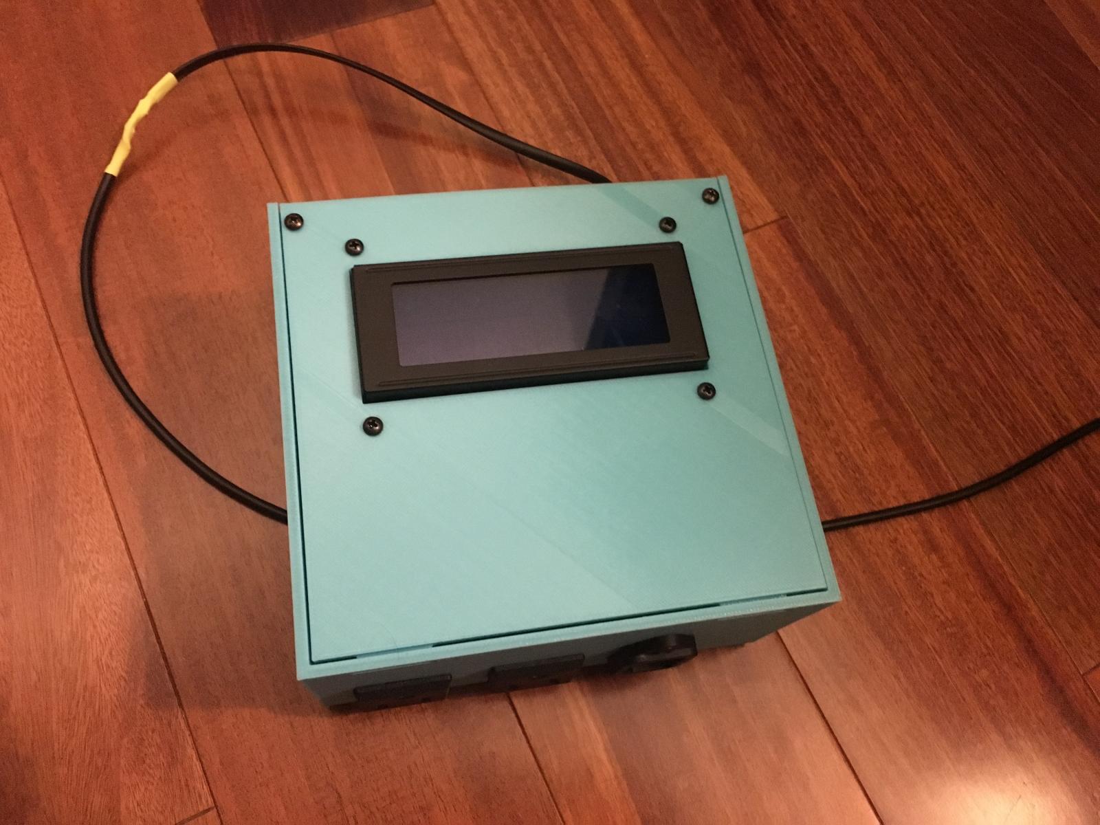
I took some time this morning and (finally!) got my enclosure assembled & wired up. Thus far, everything is looking good! I'm still working to collate the pictures I took & get a complete BOM, but the case seems like a winner. Only change I noted was that I should have added a third support underneath the PCB even if it won't have a screw going through it. Easy change.

As I mentioned in an earlier post, while working on the wiring I realized I needed a way to test the relays, LCD, etc to make sure that everything was working as intended. To accomplish this, I created a "test" image that could be flashed to the ESP8266. The image does the following:

  1. Initialize an IIC LCD panel
  2. Turn on the "cool" relay for 10 seconds
  3. Turn on the "heat" relay for 10 seconds
  4. Check if you have any OneWire parasite powered devices
  5. Loop through attached OneWire devices & print their current temperature

Basically, it tests all the hardware except the buzzer & door switch. If anyone wants, let me know, and I can add tests for the buzzer & door switch as well.


The source code can be found here: https://github.com/thorrak/brewpi-esp8266-build-test

A precompiled binary of the test script can be found here: https://github.com/thorrak/brewpi-esp8266-build-test/blob/master/bin/wiring-test.v0.1.bin
 
You know how it is ... pics or it didn't happen. :)

Yeah, yeah. Working on it! Should have everything together later tonight. It's... a lot of photos.

For now, I went ahead and put together a full bill of materials for the build:

14x #4-40 Philips Head Machine Screws
14x #4-40 Hex Nuts (Nylon not required)
2x #4-24 Philips Head Sheet Metal Screws
1x BrewPi/ESP8266 PCB (assembled)
1x WeMos D1 Mini v2/Pro
1x I2C/IIC LCD2004 LCD Display
1x 5v 2a Power Supply
1x 2-Channel Relay Board
8x Female-Female Dupont Wires
2x SS-6B Snap In AC Connectors
1x IEC-320 Male Power Inlet
9x Female Nylon Spade Quick-Connect Connectors (Optional)
Black, Green, and White Wire
Wire Nuts
4x Self-adhesive Rubber feet


I've got links to the various items in the above bill of materials in the blog post here - most things can be picked up either at your local hardware store, on Amazon, or in a few cases on AliExpress.
 
Alrighty, we're good! I've posted all the photos associated with the assembly and written up basic assembly steps. Everything is posted here.

Apologies for the use of wordpress on these -- I wouldn't, if it wasn't for the sheer volume of photos to post. Something, something, pics or it didn't happen and all. ;) Also, the issue with editing posts like the first post in the thread. ><

2016-11-13 22.57.36.jpg
 
Looks awesome! I'm also psyched because I bought the same printer. :)

I ordered the surface-mount boards, I'll give that a go so I don't have to re-design the enclosure. Worst-case I'll do what I did with the Arduino shield and offer a trade to have someone else solder them up. ;)

For the power inlet - any reason why you did not go for something with a switch like this?

https://www.amazon.com/gp/product/B00F4MFMXE/?tag=skimlinks_replacement-20

I wish I could shoulder-surf someone when they make something like that. It's got to be simple but I've so far not been able to pull it off. I can modify other things like on Tinkercad, but I'd be hard pressed to do something like that and have it work out the first time.

Like for instance - how do you know how big to make the holes for the inlet/outlets? Do you have to hunt down a drawing for that?
 
Last edited by a moderator:
Thought, i'd have a look to see how much it would cost me to get your case printed over in the UK Thorrak... it's a snip at £145, admittedly it's the first place i've looked, might look for another option...
 
Thought, i'd have a look to see how much it would cost me to get your case printed over in the UK Thorrak... it's a snip at £145, admittedly it's the first place i've looked, might look for another option...
Yikes!

Have you checked 3DHubs? I just uploaded there and got prices and I was quoted $11.99 on up to ... a lot.
 
Looks awesome! I'm also psyched because I bought the same printer. :)

I ordered the surface-mount boards, I'll give that a go so I don't have to re-design the enclosure. Worst-case I'll do what I did with the Arduino shield and offer a trade to have someone else solder them up. ;)

For the power inlet - any reason why you did not go for something with a switch like this?

https://www.amazon.com/gp/product/B00F4MFMXE/?tag=skimlinks_replacement-20

I wish I could shoulder-surf someone when they make something like that. It's got to be simple but I've so far not been able to pull it off. I can modify other things like on Tinkercad, but I'd be hard pressed to do something like that and have it work out the first time.

Like for instance - how do you know how big to make the holes for the inlet/outlets? Do you have to hunt down a drawing for that?


Nice! I love this printer -- after it gets dialed in. Apparently my definition of "squished lines" and Prusa's is not quite the same, so I was attempting to print things with the print head floating WAY above the surface of the build plate. A few chats with support later, and a newly sheepish me is back to printing.

I'll freely admit that I have no artistic ability, and 3D modeling is well beyond my skillset. What I have the ability to do is think (somewhat) logically and program, which is why I love OpenSCAD. It's free, and while a bit quirky makes sense once you start digging into it. I've posted the OpenSCAD source for all of the objects I've created on Thingiverse to make them easy to modify.

For things like the holes for the AC output, what I did was use a ruler/calipers to measure the object and then printed a small flat rectangle with just the hole I designed. If it fit, awesome - Create a function out of the OpenSCAD code I wrote to add the hole, and then reuse it in any project I want the connector in. If it didn't fit, tweak it, and reprint.

For things like holes for the AC input, I was able to find an engineering diagram of the connector which made it easy to write code for. You generally need holes to be slightly larger than they appear in most diagrams, but again - that's easy to tweak.


The reason I didn't use that specific AC input is due to a number of factors, all of which come back to the fact that this case is based on another case which I originally designed when I had a printer with a smaller print bed. There's no reason you couldn't swap out the AC input for that one you linked (or alternatively the snap in panel-mount AC output plugs for a standard AC outlet).
 
Last edited by a moderator:
Thought, i'd have a look to see how much it would cost me to get your case printed over in the UK Thorrak... it's a snip at £145, admittedly it's the first place i've looked, might look for another option...

Oh man. That's... ridiculously expensive. Printing in the states + shipping should be less than a quarter of that at most if I had to guess, and I'd assume you could find a printer locally that would be cheaper.

At that price, you could buy a cheap printer kit and print your own.
 
So, hooking up my LCD screen to the Wemos D1 - I'm using an actual D1 - not a mini - I'm having a problem and I think it is because my D1 pin is also TX.

Could this be causing my LCD not to display? Its just showing all characters boxes filled.

Appreciate any feedback guys!

EDIT: I'm a muppet.

There are actual SDA and SCL pins on this board, which has solved my woes.

Thanks anyway team!
 
Yikes!

Have you checked 3DHubs? I just uploaded there and got prices and I was quoted $11.99 on up to ... a lot.

sadly still very expensive in the UK cheapest i can see through 3d hub is £50, still good to know if i bought a 3d printer i good make the money back selling plastic skulls ;)
 
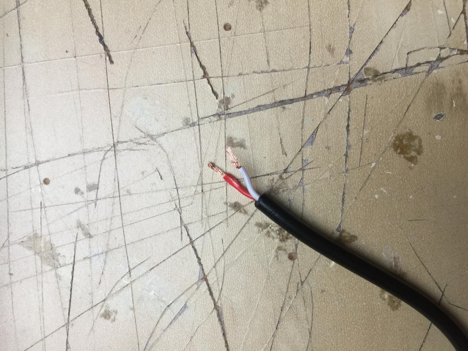
Just a little word of warning, incase there are more idiots like me out there, if you're planning on stripping back a USB cable to power the ESP8266 via USB on one of the Thorrak chips, don't assume the wiring.

I always think Red live and work the rest out.

that wasn't the case this time and another chip fried!!!

IMG_6972.jpg
 
Just a little word of warning, incase there are more idiots like me out there, if you're planning on stripping back a USB cable to power the ESP8266 via USB on one of the Thorrak chips, don't assume the wiring.

I always think Red live and work the rest out.

that wasn't the case this time and another chip fried!!!

Ouch - I wish I could pretend I hadn't done something similar in the past. Sorry to hear you're out a WeMos ><
 
So, it's been a few days, and I wanted to check in with a status update.

I haven't heard any bugs with regards to the 0.2.x firmware, so I'm hoping that version 0.61 is doing it's job. I don't have any additional features to add at the moment, so absent new ideas or new bug reports, my plan is to leave it alone for the time being. Eventually, I may add/test buzzer support, but that's remaining low on the priority list at the moment.

As far as the work on the 0.4.x firmware, the status remains the same as before. I'm still having issues with setting up OneWire sensors/assigning pins, but I can't tell if it's a communication thing or an actual firmware issue. I decided to take the circuitous route to debug it, however, and have instead been working on...

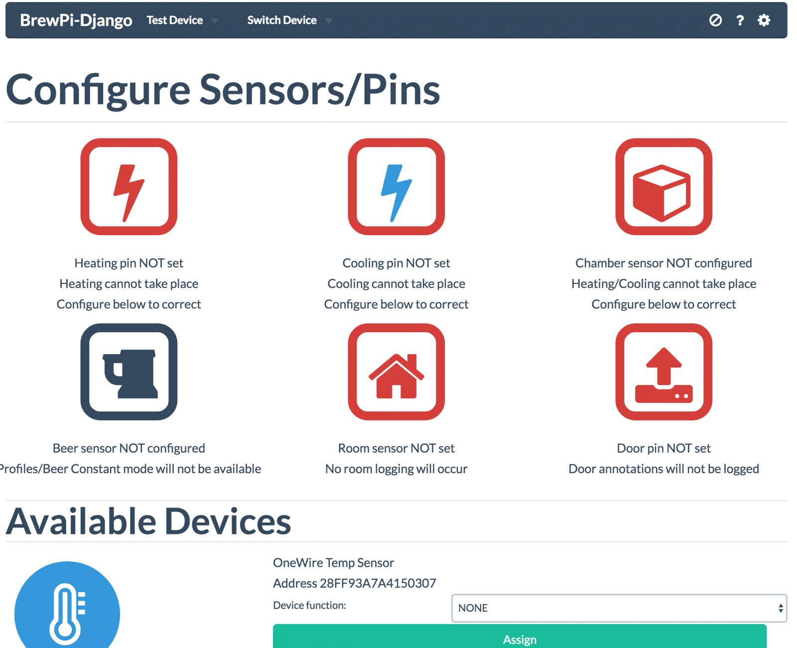
...a new BrewPi related project - BrewPi-Django. Basically, this is a complete rewrite of brewpi-www from scratch, as well as a partial rewrite of brewpi-script. The goal is to eventually make it easier to set up & manage a brand new BrewPi installation (Arduino, ESP8266, or Spark) as well as to add optional brewmometer/tilt hydrometer support. Additionally - and more importantly for my purposes - it adds multi-chamber (multi-device) support. Basically, manage all your BrewPis from a single web portal.

Once I get this project to a point where it's usable, I'll post the code to GitHub & create a new thread to discuss. For the time being, however, I'm trying to push forward to get it mature enough to be able to help debug the v0.4.x line of the BrewPi-ESP8266 firmware. ;)

Screen Shot 2016-11-22 at 12.47.09 AM.jpg
 
So, it's been a few days, and I wanted to check in with a status update.

I haven't heard any bugs with regards to the 0.2.x firmware, so I'm hoping that version 0.61 is doing it's job. I don't have any additional features to add at the moment, so absent new ideas or new bug reports, my plan is to leave it alone for the time being. Eventually, I may add/test buzzer support, but that's remaining low on the priority list at the moment.

As far as the work on the 0.4.x firmware, the status remains the same as before. I'm still having issues with setting up OneWire sensors/assigning pins, but I can't tell if it's a communication thing or an actual firmware issue. I decided to take the circuitous route to debug it, however, and have instead been working on...

...a new BrewPi related project - BrewPi-Django. Basically, this is a complete rewrite of brewpi-www from scratch, as well as a partial rewrite of brewpi-script. The goal is to eventually make it easier to set up & manage a brand new BrewPi installation (Arduino, ESP8266, or Spark) as well as to add optional brewmometer/tilt hydrometer support. Additionally - and more importantly for my purposes - it adds multi-chamber (multi-device) support. Basically, manage all your BrewPis from a single web portal.

Once I get this project to a point where it's usable, I'll post the code to GitHub & create a new thread to discuss. For the time being, however, I'm trying to push forward to get it mature enough to be able to help debug the v0.4.x line of the BrewPi-ESP8266 firmware. ;)

Awesome news, I`m sure there will be no problem getting testers :) Count me in, whenever you want. I have in fact 5 chambers today, and would love to see a better multichamber solution (y)
 
Very cool!

So that will work with all of the "standard" Arduino users as well? How about fuscus?

Still no printer here. They said 3-4 weeks and today is just three weeks. It's been FOREVER!
 
Very cool!

So that will work with all of the "standard" Arduino users as well? How about fuscus?

Still no printer here. They said 3-4 weeks and today is just three weeks. It's been FOREVER!

Yep. Anything that's compatible with BrewPi today will be compatible with this version. Theres three levels of support I'm targeting:

Maintainance - Logging, Sensor Assignment, etc
Deployment - Flashing the device, updating firmware
Specialty - Tilt Hydrometer support, Fuscus sensor setup, etc.

I'll post the code once I get maintainable support ready, as that's when it will be useful. The goal though is to eliminate all of the command line BrewPi setup - and that requires deployment support.

Fuscus is a special case, as it doesn't (yet) have sensor/device setup in the code. That said, there's nothing that would prevent either treating it as a special case and writing a script to write out Fuscus config files, or just adding native support to Fuscus itself.

We'll get there though.
 
What is the difference between all the diff boards at PCBs.io? Is there a post or a reference for them.?

There probably is awhile back, but as a reference, there's two main boards posted at the moment:

D1 Breakout - LCD TH Dupont - Breakout board which uses through-hole components, and dupont connectors for the LCD, etc. - This board requires a separate through-hole logic level converter board to use an LCD panel. I don't have the link for this board, but it's inexpensive, and available on AliExpress. By using through hole components this one is a bit easier to solder.

D1 Breakout - LCD SMD Dupont - Breakout board which uses smd components, and dupont connectors for the LCD, etc. - This board DOESN'T require a separate logic level converter to use an LCD panel. It's a touch harder to solder, but pays off in that it requires fewer components.


There is a third board which apparently disappeared from pcbs.io which replaces the dupont cables for screw terminals. If you're interested let me know and I can repost.
 
As the holiday weekend comes to a close, I wanted to post with a few status updates on where things stand.

Work is continuing on my Python/Django rewrite of brewpi-www. Thus far, the software can configure control constants/settings, configure devices, collect data, and graph that data. Missing at the moment are lesser used features such as setting fridge/beer temps, setting profiles, etc -- though I would pose that those aren't really important features for a temperature controller.

In all seriousness, however, temperature settings/management are the next features to go in, followed by a rewrite of the data graphing code (thinking about switching to highcharts?), followed by fermentation profile management. At that point I'll start thinking about getting things cleaned up & posted to GitHub. At this point, I'm guessing that's a few weeks out. After a discussion in another thread, I'm thinking that the Django rewrite may need a better name than "brewpi-django-multichamber". If anyone has any suggestions - preferably some which aren't such a mouthful - let me know.


On the firmware front, with the completion of the device management code I'm able to pick the v0.4.x firmware back up. Apparently, not a minute too soon, as Elco & Co. released v0.4.4 of the Spark firmware last week. I've already merged the changes they made into my fork, so once this is ready to install it will still be running the latest version of the firmware.

Thinking about the legacy (v0.2.x) firmware line, I think we're still pretty much set at the moment. I don't plan to make too many changes to that line unless there are bugfixes or I end up deciding to add support for something like the rotary encoder. That said -- if anyone finds any bugs, let me know! The "legacy" branch isn't abandonware in this case, despite the fact that the goal is to get v0.4.x running! ;)
 
So the python rewrite has:

Install GUI
Better device management including Multi Wemos/ Arduino support
Support for v0.4.x firmware (under development)
Support for current v0.2.x firmware

I understand there's a lot more work under the hood, but from a basic users perspective have I missed any add ons?

I have trolled this thread since the day it started and I can only say Bloody awesome work

cheers
Mike
 
Back
Top