MyPin TD4-SNR with PT100 Wiring Diagram

Homebrew Talk - Beer, Wine, Mead, & Cider Brewing Discussion Forum

Help Support Homebrew Talk - Beer, Wine, Mead, & Cider Brewing Discussion Forum:

This site may earn a commission from merchant affiliate links, including eBay, Amazon, and others.

Byrd

Active Member
Joined
May 13, 2011
Messages
44
Reaction score
5
Location
Charlotte
Before I set my house on fire, I wanted to verify things look good to accomplish the following:

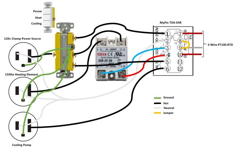
1. The single pole three switch receptacle is the master turn on/off of the PID, Heat, and Cooling.

2. To boil, I would set the TD4 into manual mode, and set my temperature for boiling which would use the SSR to turn on a 1500w element.

3. AL 1 would manage the cooling pump after flame out. When I'm done boiling, I'll set my 70 degree temperature in the PID and it'll run the 40w 120v 1/3 amp pump until it reads 70 degrees. AL 1 is a 3amp relay so this should be fine, no secondary SSR needed.

4. Managing fermentation will be completed by setting the temperature to N (70 for example) degrees like above, but instead of a 1500w element for heat, a heater blanket will be plugged in so the the blanket will be turned on/off and the cooling pump from AL 1 will be turned on/off as the temperatures dictate.

Is this possible in this manner?

Also, any help wiring in a small computer fan into this setup would be really valuable! Thanks in advance!! :tank:

BrewController_zps56bjyvfr.jpg~original
 
Do you have a function description of the three button switch? Specifically do the buttons operate like "radio" buttons (i.e. select one and only one), or are they more like select boxes (independent, select multiple, push on, push off buttons)?

How, and under what conditions, do you see the fan operating?

Brew on :mug:

Thanks for the quick reply Doug.

Power - The power switch just turns on the PID which is effectively the master power switch as the user can't use anything else without the PID being on.

Heat & Cooling - This acts as a master switch for the heating and cooling functions. If there is a boil over and I couldn't contain it, I could flip the heat off and kill all power to the element. This is much faster than using the PID.

During the boil, the power and heat switches are on (the cooling is off).

After the boil, the cooling switch is turned on and all three switches stay on for the duration of the fermentation.

Ideally the fan would only be on when the heating element (the SSR) is on. It's a DC 12v .30 amp fan.

Thanks again!
 
Ok. Looks like it should work, as long as you know how to set up the alarm programming on the MyPin.

You don't want to be cycling the fan with the SSR, as the cycle time and number of cycles will wear the fan out in short order. I would suggest having the fan on whenever the heater switch is on. So, wire the 120V AC inputs of a 12V power supply between terminal #2 of the SSR and neutral.

Brew on :mug:
 
Thanks for the quick reply Doug.

Power - The power switch just turns on the PID which is effectively the master power switch as the user can't use anything else without the PID being on.

Heat & Cooling - This acts as a master switch for the heating and cooling functions. If there is a boil over and I couldn't contain it, I could flip the heat off and kill all power to the element. This is much faster than using the PID.

During the boil, the power and heat switches are on (the cooling is off).

After the boil, the cooling switch is turned on and all three switches stay on for the duration of the fermentation.

Ideally the fan would only be on when the heating element (the SSR) is on. It's a DC 12v .30 amp fan.

Thanks again!

One thing to note is if the ssr fails, it will most likely fail open. So if it fails and you have "power" off and "heating" on you'll still have current flowing.
 
One thing to note is if the ssr fails, it will most likely fail open. So if it fails and you have "power" off and "heating" on you'll still have current flowing.

Good point! That alone is reason enough to recommend not using this design.

Brew on :mug:
 
One thing to note is if the ssr fails, it will most likely fail open. So if it fails and you have "power" off and "heating" on you'll still have current flowing.

You just had to go and ruin all the fun with your logic didn't you?! :p I appreciate you looking at this in detail.

All of the wiring diagrams I've seen for 120v are wired similar to this, they just include an 'E-Stop'. This 'E-Stop' is effectively the 'Heat' switch in my setup. I haven't seen a PID wiring diagram where if the SSR were to fail open the system would automatically know and cut all of the power (see attached). Maybe I haven't looked hard enough.

Would a Normally Closed buzzer between the heat and the power be an idea? If the "heat" is on and the "power" is off it would buzz until I turned on the power. I just can't source a NC buzzer :(

Any help? Should I go to a two switch outlet? I don't think the diagram below would solve the SSR issue. I did add the fan and a fuse.

BrewController%20v2_zpsjkyq9qor.jpg~original


image.jpg


120v ssr.JPG
 
What's the black jumper across the back of the switch for?

In the designs I create, I like to have power provided to the controller (PID, EZBoil, etc.) before power can be applied to the elements. This gives you a chance to make sure the state of the controller is such that you won't get unexpected element firing immediately on powering up the controller. The design below shows this. The main power switch applies power to the controller, but elements can be off when the controller is on. It's not possible to power the elements without the controller being on (in case of an SSR failure.) It's possible with a little more complexity to make sure that the main power cannot even be turned on if the element enable switch is on (I have published examples of this type of design as well.)

DSPR120 1 - Element 0 - Pump Volt-Amp Meter 240V only.PNG

Brew on :mug:
 
As Doug illustrates, it is common to use a contactor that uses your PID power circuit to control the main current flow to the SSR. You could easily incorporate that with your three position switch diagram.
 
The black jumper provides power to the bottom switch when the top switch is turned on. To turn the cooling on, the PID would have to be Powered on. I'm sort of guessing this is how it works :confused:

The difference between the 3 switch and the diagram above appears to be the contactor which looks like it closes the heating element circuit from power by the coil when the Elements Lighted Switch (Auber SW1 or SW16) is turned on. Should the SSR fail closed it wouldn't matter bc the coil to the contactor is Normally Open.

With that being said, this setup below seems to accomplish virtually the same thing.

1. When power is on, the jumper then enables the heat to be turned on. When the heat is on, it powers the SSR. This way, if the power is off and the heat is on, there is no current flowing.

2. The cooling no longer has a switch, but it takes power from the jumper when the PID is turned on. When the AL 1 temperature is met, it then closes the circuit and the water pump is turned on.

I hope I have this figured out! Thanks for your time and expertise!

BrewController%20v3_zps2raisokm.jpg~original
 
Got it. My confusion was that your original switch had a common side to all three switches, but in the new switch there is no common (two independent SPST switches in one body.)

I agree your new configuration meets the design considerations in my previous post.

Brew on :mug:
 

Latest posts

Back
Top