My two 5500 watt element 1 PID and SSR build

Homebrew Talk - Beer, Wine, Mead, & Cider Brewing Discussion Forum

Help Support Homebrew Talk - Beer, Wine, Mead, & Cider Brewing Discussion Forum:

This site may earn a commission from merchant affiliate links, including eBay, Amazon, and others.

bigljd

Well-Known Member
Joined
Oct 26, 2010
Messages
409
Reaction score
24
Location
Sacramento
After tons of help and ideas from P-J, Ischiavo, Kal’s website, and all of the other builds shared on this site, my build is underway!

To start, here’s the diagram I’m using for the wiring. It started as a P-J diagram but I've significantly modified it to add in 2 contactors to control current to the elements. I also threw in a 240v LED to indicate when the control panel is live.

EDIT 11/26/11: IF YOU WANT TO SKIP TO THE BIG FINISH, CLICK HERE

EDIT 7/7/12: CLICK HERE TO SEE THE UPGRADES I MADE TO THE HLT AND CONTROL PANEL

My_Panel_Schematic2.jpg


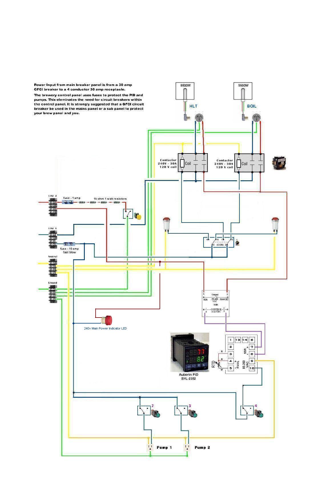
The 120v circuit in the diagram uses 14g wire and is protected by a 10 amp fuse. The element load uses 10g wire and is protected upstream from the control panel by a 30 amp 2 pole breaker in the home’s main breaker panel.

I’m going to use 80 ft of 10/3 with ground UF cable plugged into a 4 prong 30 amp receptacle mounted next to the home’s main breaker panel to run power out to a spa panel in the brew shed. The spa panel will provide GFCI protection to the e-brewery, and the e-brewery control panel will be hard wired into the spa panel with 10/3 with ground romex inside the shed.
You can read more here about wiring up the receptacle:
https://www.homebrewtalk.com/f170/how-connect-spa-panel-full-breaker-box-276680/

Here are some pictures of my build as it progresses:

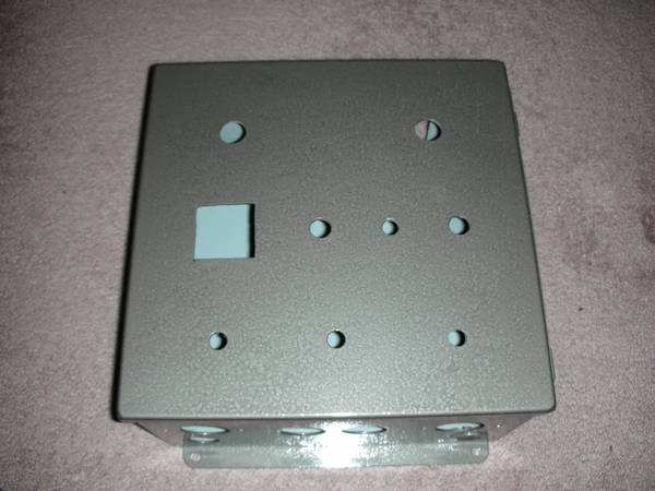
My used Hoffman 12x12x6 enclosure that I won in an Ebay auction for $26 plus $13 shipping:

enclosure_1.jpg


enclosure2.jpg


I drilled/cut out the holes and painted it with some Rustoleum hammertone finish:

DSCN20591.JPG


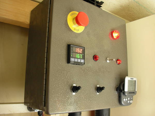
Here’s the control panel with the most of the components test fitted (later I did swap locations of the E-Stop and Main Power LED):

DSCN20601.JPG


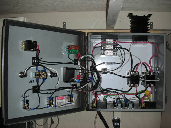
And here it is partially wired up. The SSR/Heat sink will go into the rectangular hole cut on the right hand side of the picture:

DSCN2070.JPG


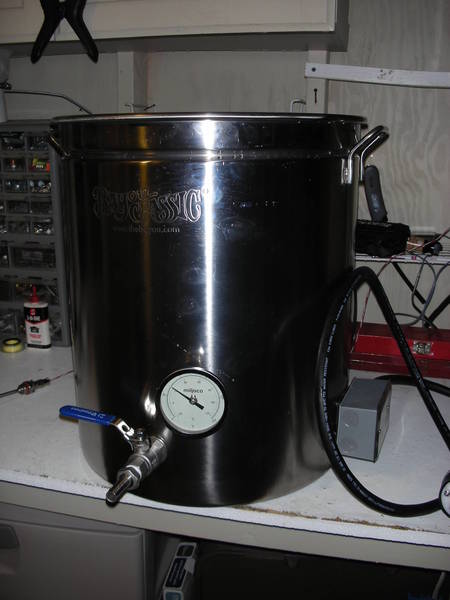
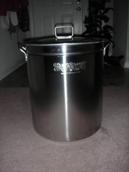
And here’s my shiny new 62 qt Bayou Classic kettle that will become my boil kettle. The keggle I’m using now will become my HLT.

DSCN2057.JPG


Feedback on the wiring diagram and setup is encouraged. I hope to finish wiring it over the next couple days so I can start testing it and maybe do a test brew on it this weekend if I can get the elements drilled and wired up by then.

I’ll update this with new pictures as I make more progress.

Thanks,

Larry
 
Where do the temp probes fit into the wiring diagram?

There will be just 1 probe wired into 3,4, and 5 of the PID controller. The probe will be mounted in the HLT to monitor strike/sparge water temps. When I switch to the BK for the boil, I will switch the PID to manual mode the probe won't be used. I'll have a thermometer mounted to the boil kettle to read the wort temps during chilling.
 
I had a similar question about the temp probe, I was wondering how you where planing on switching from one vessel to the next. Any reason why you are not going to install a locking XLR receptacle in your control panel like Kal did so when you switch from your HLT to your BK, you can simply swap the probes?

I've watched my neighbors boil kettle with run by the PID at a boil and it switches on and off quite often to maintain it at a low rolling boil. It might be quite a chore to manually run an element.

I actually won't be manually running the element - the PID will be controlling the boil in manual mode. You don't need a probe in the boil kettle to run the element in manual mode, so switching of the probes isn't necessary. The probe will be in the HLT, and I'll switch over power to the BK and run the PID in manual mode at 50% or whatever is necessary to maintain a rolling boil.
 
It's alive! Last night I wired up the spa panel and finished wiring up the control panel. Tonight after triple checking the wiring I flipped on the power and to my amazement everything worked exactly as planned. No explosions, fireballs, or meltdowns! ;) :ban:

I did some checks with my multimeter and all the voltages are correct, and the emergency stop immediately trips the GFCI in the spa panel, so I'm a happy camper.

Now I just need to mount the elements in the kettles and start testing everything under a full load.

Here's some pics:

panel_live.jpg


DSCN2075.JPG


DSCN2083.JPG


More pics to come when everything is up and running!
 
A question for you all - what's the best way to mount the heat sink on top of my control panel?
I have a rectangular hole cut out in the enclosure and the SSR slides thru the hole and is mounted to the heat sink (you can see it in the pictures a couple posts up). I tried some JB weld but it came undone when I was wrestling the control panel up on the wall trying to screw it into the wood. So now the heat sink is not secured to the enclosure - gravity is holding it in place but I'd feel more comfortable with it secured.
 
Thanks for the compliments! I'm pretty happy with how things are turning out.

I've got another update tonight - I drilled out the holes in the 62 qt Bayou Classic kettle and mounted the ball valve, thermometer and heating element. My element mount is Kal inspired, but I used a single gang box and the o-ring and nut from Bargain Fittings to seal everything from the inside.

I did a test run with 4 gal of water and there were no apparent leaks and the water heated from 67 to 150 in about 10 minutes. That is way faster than propane. :ban:

I won't complete the build this week probably, because I realized I don't have a bulkhead fitting for my keggle, and I want to go stainless so Bargain Fittings is getting another order. I can still brew on Saturday with the new e-brewery, I'll just have to use the Bayou boil kettle to heat the strike and sparge water and pump it to the HLT and MLT. No big deal.

Next week I can finish mounting everything on the keggle, mount my heat sink with either a tap and die or self tapping screws, and build a stand for my boil kettle. I'm ready for a little break since I've been working on this every day for the last 8 days. It's worth it though, and I love this stuff.

Here's some more e-brewery pron for you:

The new Electro-Bayou
DSCN2084.JPG


DSCN2085.JPG


DSCN2088.JPG


Here's my setup for this weekend. The HLT cooler will be replaced later with an electric keggle HLT. My propane burner stand will be used for my e-kettle until I can build a proper wood stand for it that's a bit taller.

DSCN20861.JPG


Cheers! :mug:
 
So... I see that extra set of contacts on your e-stop... that is a NC set of contacts. If you ran the dark green wire on the schematic that feeds the selector switch through those contacts(after the 10A fuse), you would be obeying a big rule in the one and only sticky in this forum "DO NOT DEPEND ON A GFCI TO SAVE YOUR ASS!" As an electrical engineer, I really dislike the idea of a GFCI being used as an e-stop.. (worse than using ground as a neutral in my opinion!) I have had 2 household GFCI's in my house stop responding to the test button, which is what your circuit does.. and what if a wire comes loose? no worky the e-stop? If you have that AND the NC contacts wired up, you are safe, safe, safe..
 
So... I see that extra set of contacts on your e-stop... that is a NC set of contacts. If you ran the dark green wire on the schematic that feeds the selector switch through those contacts(after the 10A fuse), you would be obeying a big rule in the one and only sticky in this forum "DO NOT DEPEND ON A GFCI TO SAVE YOUR ASS!" As an electrical engineer, I really dislike the idea of a GFCI being used as an e-stop.. (worse than using ground as a neutral in my opinion!) I have had 2 household GFCI's in my house stop responding to the test button, which is what your circuit does.. and what if a wire comes loose? no worky the e-stop? If you have that AND the NC contacts wired up, you are safe, safe, safe..

The e-stop switch I am using is a momentary spring loaded switch so running the power thru the NC contact would cut power to the contactors and PID temporarily if the switch were hit, but it would come back on again after it was released. The reason the GFCI option is used is because if something goes wrong power is completely shut off to the entire panel when the GFCI trips, not just to the kettles. It will stay off until I reset the GFCI back in the spa panel. I plan to regularly check both the continuity of the kettles and control panel to ground, and also to regularly test the e-stop button and GFCI at the spa panel. If either become ungrounded or the GFCI stop worky, then me stop brewy.
I'm assuming you never enter any home jacuzzis then, because I'm sure many of them use spa panels and it's a pretty safe bet that most homeowners never test the GFCI in it. I think the GFCI is as safe an option as any - it's not a guarantee of safety by any means, but if it's regularly tested I am comfortable with it.

EDIT: After thinking about it on my way to work, it wouldn't hurt to run the power thru the NC contact on the switch. That way if for some reason the GFCI were to fail I'd at least be able to temporarily cut off power to the PID and kettles by holding in the e-stop button. It would only take a few minutes to re-route the power thru the NC contact. I've got nothing against redundancies when it comes to safety. I think I'll add that to my list of follow ups for next week. Thanks
 
Looks awesome! This is exactly what I'd like to do. Can you give us a price break down on your build?
Thanks, I'll post a $ total and a basic parts list sometime when I'm done. For just the control panel, elements and wires I think it was around 500.
 
Looks like you need some of my control panel decals. I just sent a couple orders out this week so maybe you already ordered?

I was thinking about ordering them from you Bobby, and did visit your site a few times, but I'm probably going to just use the label maker I bought from Sprawlmart a while back. I'm just waiting until my wife has a chance to help me with it because I can never peel off the backing from the adhesive labels. She has longer nails so it's easier for her.
 
The e-stop switch I am using is a momentary spring loaded switch so running the power thru the NC contact would cut power to the contactors and PID temporarily if the switch were hit, but it would come back on again after it was released. The reason the GFCI option is used is because if something goes wrong power is completely shut off to the entire panel when the GFCI trips, not just to the kettles. It will stay off until I reset the GFCI back in the spa panel. I plan to regularly check both the continuity of the kettles and control panel to ground, and also to regularly test the e-stop button and GFCI at the spa panel. If either become ungrounded or the GFCI stop worky, then me stop brewy.
I'm assuming you never enter any home jacuzzis then, because I'm sure many of them use spa panels and it's a pretty safe bet that most homeowners never test the GFCI in it. I think the GFCI is as safe an option as any - it's not a guarantee of safety by any means, but if it's regularly tested I am comfortable with it.

EDIT: After thinking about it on my way to work, it wouldn't hurt to run the power thru the NC contact on the switch. That way if for some reason the GFCI were to fail I'd at least be able to temporarily cut off power to the PID and kettles by holding in the e-stop button. It would only take a few minutes to re-route the power thru the NC contact. I've got nothing against redundancies when it comes to safety. I think I'll add that to my list of follow ups for next week. Thanks

I think the GFCI e-stop is smart! NO system is 100% failproof. The operator needs to know the system and how to properly use it. Testing the GFCI should be a regular event. Using the GFCI as an e-stop is really no different than a shunt trip breaker. We use these all the time for the big panic button at gas stations.

Instead of running the contactor control power through the momentary switch, you could add another toggle as a secondary safety. My controllers are set up this way with a contactor that kills the main feed to the box.
 
EDIT: After thinking about it on my way to work, it wouldn't hurt to run the power thru the NC contact on the switch. That way if for some reason the GFCI were to fail I'd at least be able to temporarily cut off power to the PID and kettles by holding in the e-stop button. It would only take a few minutes to re-route the power thru the NC contact. I've got nothing against redundancies when it comes to safety. I think I'll add that to my list of follow ups for next week. Thanks


Is your e-stop momentary or is it the type that is push and stay, then twist to release? That style will keep power off to the contactors until pulled... I assumed that was the style, if it is not, then what you say is correct, adding the PID to the switch will give you a few seconds before the PID boots..

Alternatively, with a momentary e-stop, if you had a start button that activated a relay, and the relay contacts also provided power to it's own contacts, that would be a sealing circuit, and you could use the NC contacts to break it for another style e-stop.
 
To all of you that have built cool electric heating with control panels systems. Please come to my house and do this for me. Thanks.

(I really want to incorporate electric brewing - but really technically illiterate when it comes to electricity and wiring) :(
 
looking sweet! maybe one day I will have something that nice to post... until then I will continue to live through you.
 
I think the GFCI e-stop is smart! NO system is 100% failproof. The operator needs to know the system and how to properly use it. Testing the GFCI should be a regular event. Using the GFCI as an e-stop is really no different than a shunt trip breaker. We use these all the time for the big panic button at gas stations.

Instead of running the contactor control power through the momentary switch, you could add another toggle as a secondary safety. My controllers are set up this way with a contactor that kills the main feed to the box.

Now that I think about it, I already have a secondary safety toggle, since my DPDT toggle switch that I use to control the HLT or BK contactors is a On-Off-On switch, so if the E-stop doesn't work for some reason I can just flip the toggle to the center and power is cut off to both contactors.

It doesn't kill power to the box though, so it's not quite the same as yours, but I think I'm OK with it as is.
 
To all of you that have built cool electric heating with control panels systems. Please come to my house and do this for me. Thanks.

(I really want to incorporate electric brewing - but really technically illiterate when it comes to electricity and wiring) :(

No problem, I'll be right over ;)

looking sweet! maybe one day I will have something that nice to post... until then I will continue to live through you.

I'd been drooling over other's systems for about 6 months and finally decided to jump in and join the fun.
 
I did another test run last night with 7 gal of water - the water temp started at 63 and hit 150 in about 21 minutes with my pump recirculating the whole time. It was overshooting by a couple degrees, so I bumped up the set value to 165 and ran auto tune. After about 15 minutes AT finished and held the temps perfectly at 165 - I was impressed.

I'm glad I did the second test because I had a small leak at the thermometer that I missed on the 4 gal test. It was my fault because I forgot to use teflon tape on the thermometer threads, so that was an easy fix.

One other thing I forgot to share with others who may be drilling kettle holes with a step bit - wear long pants and shoes when doing it. If you wear flip flops like I was you get smoking hot shards of metal covered in lubricating oil flying off the step bit and landing on your feet (even at low RPMs). It's not a lot of fun. :D

Below is a parts list for the control panel and elements. I recommend not cutting corners on the PID or SSR and order from Auber (and not eBay) so you know what you are getting, but that's your decision. IMO, Home Depot has a better selection of electrical receptacles, plugs, ring terminals and cheaper wire/cable than Lowes, so if you have the choice I'd start your shopping at HD (YMMV).

For your more obscure parts (like resistors and cheap indicator lamps) you can nerd it up at Radio Shack. Just be aware that they will follow you around the store trying to sell you a cell phone plan - bring a big stick to club them with if they don't leave you alone. :D

I had a pretty good idea of what online prices were on stuff, so if I found things close to the same price I bought it locally, else I ordered online.

The list doesn't include the new kettle I bought, cable I used to run power from the house to the shed, breakers in the main panel, or any of the kettle upgrade parts I got from Bargain fittings, but I think it should cover most of the control panel and element parts. For more details on the Elecdirect parts, Ischiavo has a parts list on one of his threads that includes hyperlinks to most of the parts (it's a link in the 1st post of the thread linked here).

Thanks goes to P-J for the original parts list - I just changed it up with some of the parts that I added or substituted.

E_brewery_parts_list.jpg


:mug:
 
Not only does it look cool, it makes beer too! Brewed a blonde ale test batch with Centennial and Amarillo hops, and hit all my temps and gravities. It took me a little bit to figure out how to run the boil in manual mode (finally figured out you have to hit Set to change the display, then you can change the % power), but when I did it worked great. I also figured out the magnetic back on my timer sticks nicely on the control panel face, so now my timer is almost integrated into the panel.

I got my Bargain Fittings order today, so when the batch of brew was finished I built a wood stand for my kettle and then drilled out and wired up the element, probe, sight gauge, and installed the ball valve on my keggle HLT. The dip tube I bought won't fit since the element is in the way, so I'll need to modify it tomorrow.

Here's a few pics from the brew session - the next set of pics (next week) should be of the completed e-brewery. :ban:

Setting up the grain mill
DSCN2089.JPG


Heating strike water
DSCN2093.JPG


DSCN2092.JPG


Boil time!
DSCN20941.JPG
 
Looks great! Nothing like breaking in new brew equipment eh?

It was a fun day. One thing I did realize during the boil is that the storage shelf directly above the control panel funnels the steam from the kettle straight towards the panel, and water was condensing on it. I ended up moving the kettle out towards the middle of the shed so the steam could go up to the ceiling away from the panel. I was worried I'd short the whole system out on the first run, but it all worked out good.

It was kinda weird too, at how quiet it was during the boil. I'm used to the sound of the propane burner, and it was completely silent except for the bubbling wort.

I love my e-brewery!
 
Thats a good looking system bigljd. Can I ask what is the reason for the contactors? I see some people are using them and others are not.
 
Thats a good looking system bigljd. Can I ask what is the reason for the contactors? I see some people are using them and others are not.

Thanks - the contactors keep the element's full power load from going thru a switch. A switch controls a smaller 120v current - when the switch is turned on it powers the contactor coil which closes the contactor connection and allows the 240v 30 amp power to flow to the elements from the SSR.

30amps is a lot of power, and I just felt more comfortable having it controlled by contactors instead of a switch, but others have had success using switches. It's a personal choice.
 
Nice build! Nice brewspace! I used a couple self-tapping screws to secure the heat sink. JB weld is liquid duct tape...it has it's place.

Tonight I drilled two 9/64" holes through the top of the enclosure on both sides of the SSR, penetrating through the first level of the heat sink. Then I screwed #8 - 3/4" self tapping screws through the holes, and the heat sink is locked down nice and tight to the enclosure. Total cost, $0.98 for the screws from Lowes. I finished it off with a bead of clear silicone caulk around the heat sink to keep any water out in case I do something silly like spray my panel with a hose.

I've got some vinyl decals coming from Bobby to label all the switches and make it look good - then it will be finished! I'll do a final picture show of the entire setup.

If I can awaken from my Thanksgiving turkey coma I'll brew a batch on the completed system on Friday, and I'll get to put the new e-keggle HLT thru it's paces.
 
Glad you got it done. Self tappers are awesome. I always have some around. These for thicker metal:

1132125_hr4c.jpg


And these are great for plastic and sheet metal:

32141_hr1c.jpg


I am going to try to brew on Friday too. Cranberry Wheat for Christmas I think.:mug:
 
I was thinking about ordering them from you Bobby, and did visit your site a few times, but I'm probably going to just use the label maker I bought from Sprawlmart a while back. I'm just waiting until my wife has a chance to help me with it because I can never peel off the backing from the adhesive labels. She has longer nails so it's easier for her.

Well, you'll have the decals today or tomorrow.. no excuses let's see the pics!!

:mug:
 
Glad you got it done. Self tappers are awesome. I always have some around. These for thicker metal:

1132125_hr4c.jpg


I am going to try to brew on Friday too. Cranberry Wheat for Christmas I think.:mug:

That's the screws I used - they worked great.

I'm getting all crazy and doing my first lager along with my first attempt at decoction mashing. I watched BruKaiser's YouTube video and am copying that. I've got all day to kill since my wife works but I'm off. The recipe will be for a Helles - we'll see how badly I can mess this up...

Well, you'll have the decals today or tomorrow.. no excuses let's see the pics!!

:mug:

Cool, I've been looking for them in the mail this week. I'll shoot some pictures on Friday so I can do it during my brew session.
 
Thanks for sharing your build, I'm making a similar control box. I looked on elecdirect for the e-stop hardware and 240v indicator LED and couldn't find them. Mind sharing the part numbers? Thanks. Look forward to hearing how your brew goes tomorrow.
 
Thanks for sharing your build, I'm making a similar control box. I looked on elecdirect for the e-stop hardware and 240v indicator LED and couldn't find them. Mind sharing the part numbers? Thanks. Look forward to hearing how your brew goes tomorrow.

It comes in separate pieces, but here are the links. Thanks to Ishiavo for sharing this - it came from his parts list.

Estop Parts:
MUSHROOM HEAD SPRING RETURN ACTUATOR METAL RED

COLLAR & 1 NO/1 NC CONTACT BLOCK Use the normally open side to the contact block if you are doing the GFCI e stop

ROUND LEGEND PLATE, 60MM DIAMETER, PLASTIC, EMERGENCY STOP

LED parts:

BODY, INTEGRAL CIRCUIT & CLUSTER LED RED 240V AC

HEAD, RED, HIGH CONTRAST FOR USE WITH NEON OR LEDs

I may as well put the toggles here too:


2-SCREWS, ON/OFF, CHROME HANDLE, MEDIUM DUTY

RUBBER BOOT [CLOSED]

and the power distribution blocks:

LINE 2/0-14AWG 1 OPENING, LOAD 4-14AWG 4 OPENING, 1POLE

Have fun!
 

Latest posts

Back
Top