My Super Efficient 5-Gallon Mash Lauter Tun

Homebrew Talk - Beer, Wine, Mead, & Cider Brewing Discussion Forum

Help Support Homebrew Talk - Beer, Wine, Mead, & Cider Brewing Discussion Forum:

This site may earn a commission from merchant affiliate links, including eBay, Amazon, and others.

ChemE

Well-Known Member
Joined
Mar 3, 2008
Messages
596
Reaction score
20
Location
Columbia, SC
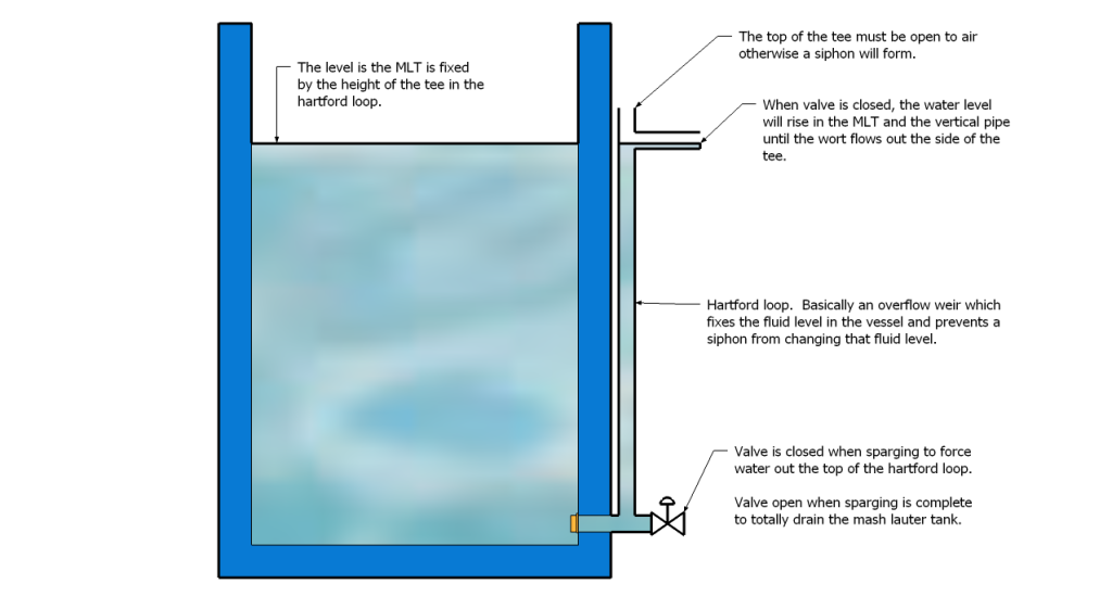
Like most good engineers I'm enthralled by efficiency. I think it is the mental challenge of trying to squeeze every last drop of performance out of a minimal amount of materials that appeals to me. One of my all time favorite engineering quotes is:
Antoine de Saint-Exupéry said:
A designer knows he has achieved perfection not when there is nothing left to add, but when there is nothing left to take away.

So motivation aside, I wanted to come up with the most efficient mash lauter tun I could. Design objectives were:

1) Accommodate 5 gallon all grain batches (except barleywine)
2) Provide good filter thickness even with low-gravity 2.25 gallon test batches
3) Minimize dead space so as not to reduce efficiency
4) Allow for fly sparging without exposing the mash to cold air
5) Allow for easy cleaning and maintenance
6) Rinse the grain bed as efficiently as possible in order to maximize efficiency

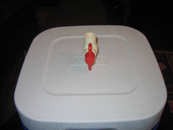
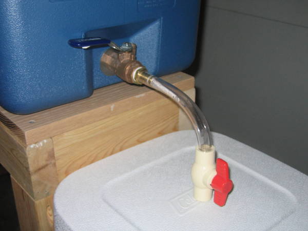
With my design objectives set, I went about educating myself and selecting a cooler which would meet my design constraints. How To Brew - Appendix D has some very good information on optimizing mash lauter tuns. I would have loved to have found a Coleman Xtreme or Ultimate Xtreme that fit the bill but these are all squat and wide. I really wanted something with a minimal footprint and good depth. My best option was a cheap no frills $20 cooler with questionable insulation shown below as the finished product.

The final product
IMG_1565.JPG


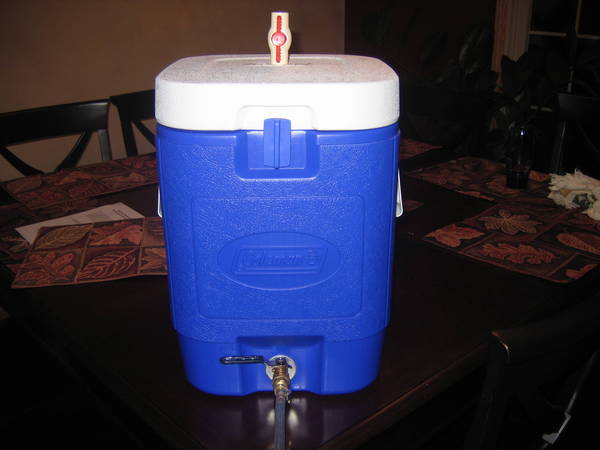
I shot the lid full of great stuff and once it was dry, I cut the excess off and sealed the injection ports with white silicone caulk. This modification is nearly undetectable but helps the cooler maintain its temperature during mashing and sparging.

With that done, I set about making a copper manifold which would drain the cooler as close to completely as possible, maximized the number of slits, and minimized the distance that sugar from any one grain would have to travel to enter the manifold. This was the winning design. Nothing is soldered because there is absolutely no need and it would only complicate clean up at the end of the brew day.

Manifold as viewed from the top
IMG_1558.JPG


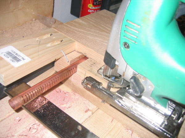
Next order of business was coming up with a way to safely cut the slits very close together which was both neat and more importantly safe. After a few hours in the shop I came up with this jig for my jigsaw.

Jig used to cut slits in copper pipe
IMG_1553.JPG


Jig in [simulated] action
IMG_15541.JPG
 
Now that I could safely and neatly cut slits at whatever spacing I wanted, I got to work cutting. A few hours later this is the result.

Bottom of manifold
IMG_1557.JPG


Notice the flexible tubing which allows the manifold to connect to an internal nipple. This lets me place the manifold on the very bottom of the cooler and yet still take it in and out for easy cleaning. The manifold fits in the cooler so tightly that even the most vigorous and drunken stirring can't knock the manifold out of place or the hose loose from the nipple.

Manifold in MLT
IMG_15591.JPG


During a few hydro tests, I let the MLT drain totally and then closed the valve and carefully poured off the remaining water into a Pyrex measuring cup. Average dead space without tilting the MLT was a scant 0.03 gallons. Perfect (or close at least).

Next I wanted to ensure that I could efficiently fly sparge without having to expose the mash to cold air. That and an integral sparge manifold is just easier to use as it is always set up and never in the way. This was easily constructed out of 1/2" CPVC and held in place by a ball valve on the top of the lid. Everything here is friction fit to allow for easy disassembly and cleaning.

MLT lid with integral sparge manifold
IMG_1563.JPG


Top of MLT with ball valve inlet to sparge manifold
IMG_1564.JPG
 
HLT plumbed into the MLT
IMG_15681.JPG


MLT fit into my compact three-tier brew system
IMG_1566.JPG


So that's it. I'm still dialing in my process but the fist two batches I've brewed with this yielded brewhouse efficiencies of 86% and 92% with original gravities of 1.043 and 1.074 respectively. So clearly this equipment is able to deliver very good efficiency with big beers.
 
Thanks Revvy. I read hundreds of threads here this summer as I was plotting and scheming so I would be willing to bet I pilfered the idea from one of you.

As any good engineer, I've already started a mental checklist of all the aspects of this project which could (and eventually will) be further optimized.
 
What capacity is that square cooler? It looks like a 5 gallon.

ANd you will put together a parts list won't you?

Yup, 5 gallons. Too bad Coleman doesn't make the Ultimate Xtremes in this aspect ratio and in 5 and 10 gallon volumes.
 
sorry, I put the wrong picture up there. It's supposed to be the view of the manifold with the inside drain tube connected to it

So how do you only lose .03 gallons when you drain from the tun? The way you have the draining tube under the manifold makes it look like your manifold wouldn't be completely on the bottom of the cooler. Doesn't this matter?

Great work by the way!!
 
Wow, that looks almost Identicle to mine, except I used CPVC instead of copper (cuz im poor) I used the 12 gallon Cooler cube though. I get excellent efficiency as well.
 
sorry, I put the wrong picture up there. It's supposed to be the view of the manifold with the inside drain tube connected to it

So how do you only lose .03 gallons when you drain from the tun? The way you have the draining tube under the manifold makes it look like your manifold wouldn't be completely on the bottom of the cooler. Doesn't this matter?

Great work by the way!!

if you look at the bottom of his cooler thee is a runout in there where the drain line fits into
 
Exactly. There is a little depression in an otherwise flat bottom where the tube rests. At the bottom of the depression is the drain spout. I looked specifically for a cooler designed this way (and most of them are) in order to allow for complete draining. The manifold is pressed firmly into the bottom of the cooler and flat against the bottom. Only that tube would fit into that shallow depression. I had to be careful what nipple I used so that everything fit without pushing the manifold up off the bottom and thus creating needless dead space.

I'm going to Dremel a few slits in the bottom of that plastic tube later today. I think I can shave my dead space even further!
 
i have pretty much the same setup as you , but im using the 5 gallon for the HLT and the larger cooler for the MLT, and i used cpvc for the collection manifold in my MLT but its pretty much the same.
 
very nice, you have given me some ideas when I get around to upgrading mine.
 
I may be way out of my league here, but I'd really like to graduate from my Mr Beer to this.

Crazy?
 
I may be way out of my league here, but I'd really like to graduate from my Mr Beer to this.

Crazy?

Nope - all you gotta do is a little research and you can be good to go with all grain. It really isn't any more difficult, it just takes a little longer and a little more attention to detail.
 
I may be way out of my league here, but I'd really like to graduate from my Mr Beer to this.

Crazy?

You're not crazy at all. Prior to putting this together, I was brewing with my Mr. Beer too. The "various extract batches" in my signature were uber-expensive Mr. Beer kits. The beers I'm making now taste so much better, are so much cheaper, and are a hell of a lot more gratifying. Go for it. What do you have to lose?
 
Jonnio said:
Nope - all you gotta do is a little research and you can be good to go with all grain. It really isn't any more difficult, it just takes a little longer and a little more attention to detail.

You're not crazy at all. Prior to putting this together, I was brewing with my Mr. Beer too. The "various extract batches" in my signature were uber-expensive Mr. Beer kits. The beers I'm making now taste so much better, are so much cheaper, and are a hell of a lot more gratifying. Go for it. What do you have to lose?


Thanks, Guys. It just seems like a much better investment than the starter kits I've been looking at. I think I'd end up going to this anyway....
 
I like this but I have a question for those of you with internal sparge arms or sparge water manifolds.

How do you keep tabs on the level of liquid inside the MLT if the lid is on?

Presumably you don't want to be draining from your HLT into your MLT at an excessively high rate and put too much water on top of the grain bed, yet you also would not want to allow the grain bed to run dry.
 
practice and experience.. after a while you know about how far to turn your valves to get the right flow rate

Each grain bed is going to be slightly different though. I also seconds the question. Without being able to see how can you determine your water in compared to wort out? Even with the practice and experience answer, you need to be able to see the first few times to gain the practice and experience.


Off topic Mirillis, My inlaws live down the road from you on 36 in Covington!! A whopping 21 minutes. we should brew sometime when I'm up there. I'll bring the FIL and BIL down.
 
Just thinking out loud, but would efficiency increase even more if you had the outlet from the copper manifold parallel to the arms with the slits? When i made my manifold (albeit rectangular) people advised to have the outlet in line with those (or at least the long axis).
 
I'm going to Dremel a few slits in the bottom of that plastic tube later today. I think I can shave my dead space even further!

I burned my face with a flying bit of tubing that was molten by doing just that. Wear a face shield.

I have an igloo marine cube thing that you could use for a similar-but-larger-scale for ten gallons I bet.
 
I like this but I have a question for those of you with internal sparge arms or sparge water manifolds.

How do you keep tabs on the level of liquid inside the MLT if the lid is on?

Presumably you don't want to be draining from your HLT into your MLT at an excessively high rate and put too much water on top of the grain bed, yet you also would not want to allow the grain bed to run dry.

I plan on adding a Hartford Loop. These are commonly used in saltwater aquarium skimmers to maintain a constant water level in a vessel despite flow going both in and out. I tried to make how these work clear with notes on the SketchUp model but let me know if anyone has any questions. I really can't believe no one seems to use these for fly sparging. Once the height of the tee is set, that's it. There is no possibility of the fluid level changing.


Hartford loop
Hartford_Loop.png
 
I burned my face with a flying bit of tubing that was molten by doing just that. Wear a face shield.

I have an igloo marine cube thing that you could use for a similar-but-larger-scale for ten gallons I bet.

I used a utility knife rather than a Dremel but thanks for the heads up!
 
Just thinking out loud, but would efficiency increase even more if you had the outlet from the copper manifold parallel to the arms with the slits? When i made my manifold (albeit rectangular) people advised to have the outlet in line with those (or at least the long axis).

I'm not sure that at such incredibly low flow rates there is enough resistance to flow in the elbows to make any difference.

Really what you want to make sure of is that there is no easy path for the wort and sparge water to take. You don't want the middle leg of your manifold to have no resistance to flow (pressure drop for other chemical engineers) and all the others to have a high back pressure. This would set up a scenario in which the high back pressure legs would essentially be stagnant and all the flow would travel through the low back pressure leg. This would prevent the grains near the high back pressure legs from being washed of their sugars.
 
Once the height of the tee is set, that's it. There is no possibility of the fluid level changing.

That's a good idea, but wouldn't you want/need to have the height of the outlet of the loop be adjustable depending on the size of your grain bill? I can't see an English Bitter and a big Barleywine having the same setting.
 
Yup. You would definitely want that height to be adjustable. If the bottom most valve is a true union ball valve, then you can loosen one side of the union, rotate the vertical, and tighten the union. The height of the tee would sweep out a circle and can be set at any desired height to accommodate any grain bill which would actually fit in the MLT.

True union ball valve
cepex-TU-34-ball-valve.gif
 
I have the 10G version of that cooler, but with a bazooka screen instead. What I really appreciate is the design for the jig to cut the copper tubes. I was trying to think of an effective way to do that when I build my manifold for my next NLT, and a jigsaw with that set-up is an awesome solution. Thanks.
 
...What I really appreciate is the design for the jig to cut the copper tubes. I was trying to think of an effective way to do that when I build my manifold for my next MLT, and a jigsaw with that set-up is an awesome solution. Thanks.

My pleasure. I seriously stood out in my shop for a few hours trying to come up with that jig. I'm glad someone else can benefit from it. I haven't taken it apart yet. If anyone needs more pictures in order to recreate it, I can certainly snap some and post them up.
 
I like the way you think ChemE. By the time I build my MLT I'm sure I'll steal a good deal of your ideas and others garnered from this site and others.
 
I plan on adding a Hartford Loop. These are commonly used in saltwater aquarium skimmers to maintain a constant water level in a vessel despite flow going both in and out. I tried to make how these work clear with notes on the SketchUp model but let me know if anyone has any questions. I really can't believe no one seems to use these for fly sparging. Once the height of the tee is set, that's it. There is no possibility of the fluid level changing.

When you are sparging with this method, would the runnings collect into your brewpot straight from the outflow of the hartford loop? I'm a bit confused with your flysparging method. Do you have a predetermined amount of sparge water in the large HLT, and eventually drain it all out into the kettle?
 
Exactly. The runnings from either the top or the bottom of the hartford loop would drain directly into the boil kettle. The HLT is filled with a specific volume of water and so everything runs through the grist and drains into the boil kettle. The amount of water needed is pretty easy to figure. It is just your boil volume plus your predicted grain absorption volume. My last two brews I nailed this using the 0.1 gallon / pound rule.
 
ChemE - Loving the Hartford loop here!

I see how the rotation of the loop could solve the problem of variable heights that one would experience with different batches but I wonder if there is another solution to overcome this without having your loop sticking way out to the side of the MT when you need to have the level of the upper drain low? Does anybody know if there is a product that could be extended straight up to adjust for different levels needed in the MT?
 
I haven't gone all grain yet, so take this with a grain of salt...

After reading this thread last night I was thinking about the hartford loop. I was under the impression that proper sparging depended on some negative pressure at the drain. This, of course, is generally provided by siphon or pump. I've seen stuck sparges reported when a drain tube is omitted (leaving just a ball valve, sans tube).

To restate: My concern is that there won't be enough pressure on the grain side (generally provided by 4+ inches of water) with the hartford loop in place.

I love the idea, and hope it works (I'll "borrow" it if it does).

My brain needs coffee....
 
Back
Top