• Please visit and share your knowledge at our sister communities:
  • If you have not, please join our official Homebrewing Facebook Group!

    Homebrewing Facebook Group

My homebrew stirplate

Homebrew Talk

Help Support Homebrew Talk:

This site may earn a commission from merchant affiliate links, including eBay, Amazon, and others.
Cool to see that I am not the only one using the old pc power supply, and a pc fan speed controller. If you are ripping apart old hard drives anyway, why not ?!

Ok, so I have tried a few configurations now, and nothing is working perfectly for me.
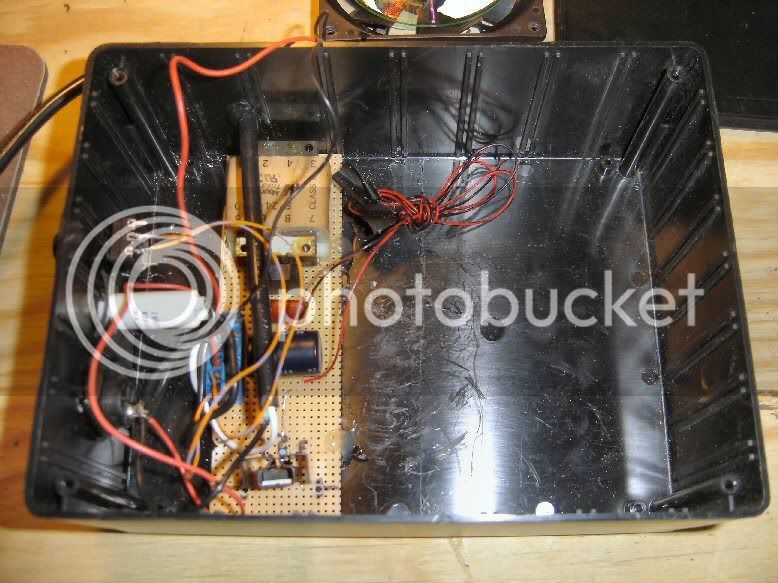
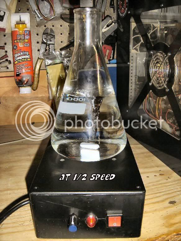
The one that is working the best is the 120mm fan, there is a rubber washer, and a flat washer on top of that, both about the size of the hub of the fan... these are glued on, and then i am putting "rare earth" magnets from Rocker Woodworking on there. The big problem seems to be the 2" stir bar. If you are looking down on the magnets as they spin, the outer edges of the bar match up with the outer edges of the spinning magnets, so the bar is pretty much dead even over the top of the entire field. Since the bar is so heavy, if there is anything at all that causes it to wiggle, it starts dancing all over the place and sooner or later flies off. I am thinking that a shorter bar will fix that, as it will be "trapped" inside the field, even if it tries to dance around, where the big one can get its fat butt outside the field...

So now I just have to order up a shorter bar and wait a week or so for it to show up.
So much for testing this weekend :mad:

Well, one of these days soon I will snap a few pics and upload so that you can see what I am talking about...
 
so i came up with another idea...
i grabbed a 4" hole saw, and cut out a disk of polycarbonate, and
laid that on top of the fan to see how it would work...
better, but still not as big as i would like... (no puns, please)
some more thinking and I thought hmmm...
cd...
so I sandwiched the polycarb between two cds...
closer, but not quite there...
needs to be taller, to clear the sides of the fan...
two more polycarb disks and we are good to go...
strong, light, nice wide area to mount magnets to...
next problem was not getting it perfectly centered on the fan when mounting...
this next part is not OSHA approved,
nor is it approved by your insurance company, your wife, or anyone else who cares about you...
if you are not an experienced wood turner, just quit read now...
if you are an experience wood turner, be smarter than me and don't do this...
so I spin the thing up to full speed, and grab sharpie, and mark out the widest true circle that i can...
next I grab a razor blade, use a file to put a nice bur on it, and begin slowly shaving down the disk...
like I said, don't try this...
not a smart thing to do...
but it worked...
I now have a perfectly round platform for mounting my magnets, which I will do tomorrow afternoon.

and no, no beers were killed in the making of this method, nor was any blood shed (though I came close once):drunk:
 
Wow. You guys have no clue how much trouble I had.

I tried two big magnets on each side and I can only guess that the magnetic field was too small for the stir bar to stay in it.
One small magnet and I had trouble not shooting the stir bar to the sides.
One big magnet and I guess I got it off center which meant that the stir bar was doing circles as opposed to spinning on itself, which would throw it off to the sides as well. It would work ok for water, but not for the starter. Now I'm desperate so I start thinking of really weird things to try.
I tried mounting a CD onto it (as the last poster did) to have a bigger surface... didn't get it centered so that didn't work.
I retried mounting two big magnets... again didn't work.
I retried mounting one small magnet, didn't work.
I retry one big magnet. BAM I get 'er centered right off the bat, put the starter back on and I get lovely movement. It's been spinning great for about 8 hours!

Thanks a lot for the original idea!
 
wow, I am glad to see I am not the only one fighting with this simple project. I tell ya I found 2 of these dang stir plates about a month ago and they were $45.00 each. I should have grabbed them, They were lab quality stuff.

I am wondering why is it the need for the spacers etc? I have not had any issues with a single magnet and getting a 1 inch spin bar going and stable with no issues. I just have the Hard drive magnet mounted to the fan and the things seems to be working fine. I would say I am getting a good spin in water 19 out 20 times trying, and that would be to full RPM.

I am not sure how this is going to work with the a pitch in it, but we will see here real soon.

As far as I am concerned any excuse to sit in the work shop and drink a few home brews, is a good one!

Next is the case, I will send some photo's once all the junk is mounted etc.
 
I have built several of these and may have the solution to your problem or maybe problems.
1. You need fairly powerful magnets, the little round disks R Shack sells will work but I had to have four on each side.
2. The magnets must be mounted north side up on one side and north side down on the other. Which is which doesn't matter as long as they are opposite. If you are using more than one magnet on each side make sure all of them are oriented correctly. All north up on one side and all north down on the other.
I didn't fool around with mounting a substrate to the fan to mount the magnets on. They are glued directly to the fan hub. If the fan seemed to vibrate I repositioned the magnets till it was smooth again.
Mine have all worked flawlessly using 1/4 X 1", 5/16 X 1 5/8 and 3/8 X 1 1/2 spin bars.
If you just can't get them to work shoot me a message, I have some for sale.
 
So you got the little round magnets in the R shack, I saw them but I had these so i was trying with them I have them working now. So I am going to stick with these for now.

But thanks for the info, I will keep you in mind.
 
Stirplate V2. Stirbar is 1" from MoreBeer. V3 will have a LED panel to show RPM

The Guts
inside2.jpg

Test 2
test2a.jpg

Stirplate V2 with non skid pad
V2.jpg


:rockin: Stir on my brothers!
 
Thanks but MrSalty was my inspiration. I just read this thread and up and built it. The main problem was figuring out the magnets. I deviated from the original by building the entire power supply internally. I had plenty of cell phone adapters but I just thought it more easier to make it self contained. If you want a schematic I can post it up but I have to draw it out yet.....
 
If you want a schematic I can post it up but I have to draw it out yet.....[/QUOTE]

I would love to see a drawing and pictures of the board (top and bottom). Not great reading schematics, I do better with pictures.

thanks

tom
A parts list would be nice also
 
I wanted to do more pics as I was going along but I didn't really think any emphasis was on the circuit. It seems that most talk was about magnets and stirbars. I also don't teach electronics very well. But here is what I have.

:mug:

schematic.jpg
 
For what it's worth to anyone struggling with a "spun-out" stirbar- A huge breakthrough for me was to get the magnet closer to the bottom of the flask. I am using one magnet from a hard drive, velcro'd on the center of the fan hub (for easy adjustment). My stir plate is constructed with 1/8" hardboard, including the top. This originally put the magnet a total of about 1/4" away from the stir bar itself. I ended up cutting a 4" square hole (same size as fan) in the top of the stir plate and jacked up the PC fan as close as possible to the flask bottom without the magnet hitting the flask. Viola!! For me, this solved two big problems:
1) it provides much greater magnetic strength to hold the stir bar in place
2) because of the greater magnetic force, it minimizes the fan speed down to a reasonable level

Adjustment of the magnet on the fan hub to get the bar to spin in a perfect circle is pretty crucial too, especially when you crank up the speed.

I am now able to spin a 2" stir bar in 2L without issues, not to mention a good vortex!

Cheers!
 
Would you have any intrest in making a stirplate for me if I paid for the parts and your time and effort? I would attempt to put this together myself but my eyesight is not very good so I am not sure of how well it would turn out. I wont need it until sometime after the 1st of the year.

Let me know.
 
Building things for others is really not my gig, but there are others on this forum that have built stirplates for a fee. I think that Yuri dude builds them for folks. Check the threads. Good luck!
 
ChrisS said:
Would you have any intrest in making a stirplate for me if I paid for the parts and your time and effort? I would attempt to put this together myself but my eyesight is not very good so I am not sure of how well it would turn out. I wont need it until sometime after the 1st of the year.

Let me know.

Contact Yuri,
He may have some already made and ready to ship.... A top notch product so I read.
 
Need a little help - no need stating that even though i can build stuff i have close to no idea about electronics.

2 questions....

1. Guy at electronics store was out of ceramic capacitros, and gave me a plastic one instead. Will this work, and does this capacitor have no polarity ?

2. What is in, adj and out on the LM317

Electr.jpg


Cheers
Jakob
 
I did it !!!!

Who would have thought i could actually put together an electric circuit. Now all i need to do is get and mount some magnets, and i am stirring !

Thx salty, and scimmia for the data !

Cheers
Jakob
 
MrSaLTy said:
This circuit can vary the voltage from about 1.3V to just under 12v I recommend this if you have a little electonics knowledge and know how to solder. Here is an EXCELLENT tutorial on how to build this circuit with component placement and everything. I have a list of parts etc at the end of this post.

http://casemods.pointofnoreturn.org/vregtut/tutorial-full.html

This doesn't seem to work when I click on the link. Does anyone have another link for it or something very simular?
 
nduetime said:
This doesn't seem to work when I click on the link. Does anyone have another link for it or something very simular?

Their homepage says "Scooping up the ashes from a power surge; please stand by." so I'm assuming it'll be back soon.
 
pbowler said:
Sorry to interrupt, but this may be helpful.
variable speed Case Fan
http://www.newegg.com/Product/Product.asp?Item=N82E16835220013
looks like 90% of the work is done already
$17

Price is down to $12.29 each with FREE shipping. Pulled the trigger on two of them - the other is for my already- SilverStone brand PC case! :D

Now I just need a box, magnets, and stir bar. Have the power supply somewhere in a box at home.
 
MrSaLTy said:
This circuit can vary the voltage from about 1.3V to just under 12v I recommend this if you have a little electonics knowledge and know how to solder. Here is an EXCELLENT tutorial on how to build this circuit with component placement and everything. I have a list of parts etc at the end of this post.

http://casemods.pointofnoreturn.org/vregtut/tutorial-full.html

Okay...so I couldn't wait and I went out to my local Radio Shack and purchased all the stuff for lots of money. Now I want to start but the link doesn't work. Each time I click on it it tells me the server can't be found. I type in pointofnoreturn.org but I get the ash message as previously stated. So here I am with parts on hand and wanting to start this as my first project in soldering/small electronic components. Mrsalty, do you happen to have the information (component placement, etc.) saved anywhere else that I might be able to access or that you could email me? I know there is a photo and schematics, but like I said this is my first attempt at something like this and I don't want to ruin all those pretty, little, expensive parts that Radio Shack overcharged for. Please!!!???!!!
 
nduetime said:
Okay...so I couldn't wait and I went out to my local Radio Shack and purchased all the stuff for lots of money. Now I want to start but the link doesn't work. Each time I click on it it tells me the server can't be found. I type in pointofnoreturn.org but I get the ash message as previously stated. So here I am with parts on hand and wanting to start this as my first project in soldering/small electronic components. Mrsalty, do you happen to have the information (component placement, etc.) saved anywhere else that I might be able to access or that you could email me? I know there is a photo and schematics, but like I said this is my first attempt at something like this and I don't want to ruin all those pretty, little, expensive parts that Radio Shack overcharged for. Please!!!???!!!

All the diagrams you need are already in this thread. See post 1 and post 22. There's not much more to it - I'm completely incompetent with electronic parts, and I can still kind of get what MrSalty has drawn out.
 
chriso said:
All the diagrams you need are already in this thread. See post 1 and post 22. There's not much more to it - I'm completely incompetent with electronic parts, and I can still kind of get what MrSalty has drawn out.

Of course I have found the important information throughout the post regarding the schematic and even the picture to show what it looks like. However, I'm more curious about the underside of what the board looks like, so I can make sure I'm doing it correctly.
Because this is my first project, I have no other experience, I've consulted the web to hopefully find answers to my question. Since the board suggest in the parts is a general purpose pc board, I'm left wondering what the underside (copperside) of the board looks like either half way done or when completely finished.
I would assume these boards are also called Stripboards right? However, based on the photos I've seen of stipboards, there should be solid strips of copper that run the width of the board. However, the pc board listed for this project does not have these. Only each hole is surrounded with copper.
I know it is not PCB (printed circuit board) which means there are no guide lines to help make sure things are in the right spot which is pretty important according to http://www.kpsec.freeuk.com/stripbd.htm Appearantly, vertical placement errors can cause problems on stripboards. I'm trying to aviod those.
Also, that same site states that components can be connected to one another by use of uninsulated wire. Since no pictures of the underside (copperside) of the board were supplied, I wondering if that was how this poject was done.
As easy as this project is and sounds, I have questions. Does it mean that I shouldn't attempt it, no! I'm trying to learn and am only asking for some help along the way.
 
nduetime said:
Of course I have found the important information throughout the post regarding the schematic and even the picture to show what it looks like. However, I'm more curious about the underside of what the board looks like, so I can make sure I'm doing it correctly.
Because this is my first project, I have no other experience, I've consulted the web to hopefully find answers to my question. Since the board suggest in the parts is a general purpose pc board, I'm left wondering what the underside (copperside) of the board looks like either half way done or when completely finished.
I would assume these boards are also called Stripboards right? However, based on the photos I've seen of stipboards, there should be solid strips of copper that run the width of the board. However, the pc board listed for this project does not have these. Only each hole is surrounded with copper.
I know it is not PCB (printed circuit board) which means there are no guide lines to help make sure things are in the right spot which is pretty important according to http://www.kpsec.freeuk.com/stripbd.htm Appearantly, vertical placement errors can cause problems on stripboards. I'm trying to aviod those.
Also, that same site states that components can be connected to one another by use of uninsulated wire. Since no pictures of the underside (copperside) of the board were supplied, I wondering if that was how this poject was done.
As easy as this project is and sounds, I have questions. Does it mean that I shouldn't attempt it, no! I'm trying to learn and am only asking for some help along the way.

AHA - sorry. I misunderstood your question. My apologies. :)
 
chriso said:
AHA - sorry. I misunderstood your question. My apologies. :)

Do my questions make any sense? I know I have a tendency to ramble on and talk too much. Sorry about that.

It appears there are wires from holes to holes but it's hard to make out with all of the wires hovering above and around in the closeup picture.
 
nduetime said:
Do my questions make any sense? I know I have a tendency to ramble on and talk too much. Sorry about that.

It appears there are wires from holes to holes but it's hard to make out with all of the wires hovering above and around in the closeup picture.

Your questions make sense, I just read your OP wrong. I think they are soldered with thin wire between each terminal. I can't tell for sure, either. Sorry I don't have more info on this. Hoping either Yuri or MrSalty will jump in....

Here's another good article - but again with no bottom shot! http://brewiki.org/StirPlate
 
I've got my stirplate mostly together, but I'm running into a couple of minor issues.

Parts used are:
14092-stirplate.jpg


1) Fan spins too fast. I used the pre-assembled Silverstone 120mm fan linked to earlier in this post, which starts at about 800 RPM and goes up from there.

2) Magnet troubles. Using the tiny RadioShack rare earth magnets, it is almost IMPOSSIBLE to glue them on because when you place one magnet, the one next to it either moves away and falls off the fan, or it flips on top of the magnet you're trying to place. Harvested a couple of Hard drive magnets, but I need to seperate them from their brackets still.

3) Broken f'ing power jacks. I've gone through two, I need to go to RadioShack for the fourth time in two days. The first one had the ground post break off, the second one had the ground contact inside of the jack bend in half when I tried to plug in the power cord. Cheap f'ing jacks. Grr. And they're $3.20 each, too. Rrrrrrrr.

So my biggest question is .... to get my rotation speed down to an acceptable range, should I go get 1 more potentiometer (that will be run at about 50%) and add it to the circuit? Should it go between the existing knob and the fan (its own circuit) or between the power connector and the fan?

Finally, does it matter what kind of potentiometer I get, in terms of resistance? What's the "right" number?

I need to leave for R.S. pretty soon but I will wait as long as I can if anyone knows the solution to my quandrary. Otherwise, I might just buy 3 or 4 different pots and see which winds up best. Not preferable, but it would work.

Thanks y'all!
Chriso
 
You may be able use a lower dc input voltage with that fan to slow it down. Depends on the guts. Could be a cheap and quick solution.
 
Found another wall wort in my pile of cables. This one is 7.5V, 1000mA. I'm a bit worried about the amperage. Oh well. This one is closer. It spins 3 or 4 times then loses it.

Two things I forgot to mention in the last post - The stirbar is the type with a ring down the center. I thought I read someone else saying that that gave them grief, but I can't recall. The other thing is that the bottom of the 1000ml Pyrex flask is indeed slightly concave.

I should've just bought one from Yuri. Rrrrrrr. I don't do well with small things.

Edit: Also, I'm down to only one hard drive magnet. I broke the other trying to get it off of its mount. Today has not been so good for this project. I'm tired of breaking something new every time I fix the last problem I caused. >_>
 
Back
Top