My FULL-ON electric build thread

Homebrew Talk - Beer, Wine, Mead, & Cider Brewing Discussion Forum

Help Support Homebrew Talk - Beer, Wine, Mead, & Cider Brewing Discussion Forum:

This site may earn a commission from merchant affiliate links, including eBay, Amazon, and others.
how are you planning on tuning your PID loop?

There are subVIs to implement auto-tuning but I have not explored much with those. I have a plant simulation setup and have basically been manually tuning the loop. Hopefully by the time this is ready to rock I will understand the autotuning feature with greater detail. Either way, my front panel will have the parameters buried in it some where so I can update it on the fly if needed...
 
Looks like it's gonna be a one of a kind, great build.

Interested to know how all this talks back to labview. Is it simply a DAC in your PC monitoring some sensors. Do you even use a DAC? Is Labview the only software package you need to monitor and control a setup like this.

I hope you're a process control engineer or you know way to much about this stuff:)
 
The ball valves are getting their own embedded control boards that handle the motor control and position feedback, I will send them a 0-100% command.
The pumps are still a major TBD part of the brewery, soon as I figure out the torque/power required to run them the motor selection can begin. I am hoping to use some large stepper motors as they are relatively easy to control and monitor position.
When the elements are in Hand or Auto mode they will be run by a SW controlled PID loop. In PWR mode they are run with a manually selected PWM duty cycle using a potentiometer on the front panel.

Wow, quite ambitious! I've been daydreaming of doing something similar, but with a little less automation. You're an inspiration to us all...

Are you building the valve's servo boards yourself? Once you've got fully adjustable valves, do you think the fully adjustable pump controls are still necessary? Is your microcontroller being used as the I/O board (ADC, DAC) for labview?
 
Wow, quite ambitious! You're an inspiration to us all...
I would hold such kind words until I can actually make a significant portion of this thing work. Looks good on paper, but reality can be a tough one.

Are you building the valve's servo boards yourself? Once you've got fully adjustable valves, do you think the fully adjustable pump controls are still necessary? Is your microcontroller being used as the I/O board (ADC, DAC) for labview?

The valve boards I am building myself. I have the schematics sitting at about 90% and the mechanical layout of the PCB is also at about 90, just need to route it once the schematic is complete.

Since my goal is to build a pair of peristaltic pumps I would like to control them as a means of monitoring how much volume has been pumped. I don't have any plans on implementing level sensors for the MLT or the BK but with a peristaltic pump I should be able to roughly track the fluid levels. This may be too much work and I will have to redesign for a different set of pumps -- not throwing in the towel just yet.

There isn't a whole lot of analog going on in this setup, temp sensors and valves will be digital. The microcontroller will act as the DAC/ADC for labview handling all of the low level functions (SPI, I2C, PWM etc).
 
There isn't a whole lot of analog going on in this setup, temp sensors and valves will be digital. The microcontroller will act as the DAC/ADC for labview handling all of the low level functions (SPI, I2C, PWM etc).

Have you selected the digital temperature sensors? Are you using a master temperature sensor IC with remote transducer/diodes? Looking into this myself, would love to hear how you're planning to monitor temperature...
 
Have you selected the digital temperature sensors? Are you using a master temperature sensor IC with remote transducer/diodes? Looking into this myself, would love to hear how you're planning to monitor temperature...

I picked up a 10 pack of Dallas 1-Wire DS18B20 sensors and they work well. No fancy signal conditioning or cables required and the accuracy is good enough for me. I purchased some thermowells from Derin at BrewersHardware to solder into triclamp caps. The LPCExpresso board will talk directly to the DS18B20's, being a 1-wire sensor you can pretty much expand the sensors to as many as needed without HW changes.
 
Thanks for the link. I've ordered a few of these to play with. Glad to see that BrewersHardware sells these already embedded in the sleeves, very handy!
 
So i'm working on a similar design as yours, but a little simpler.

I'm planning to use an Arduino for temperature measurement and PWM to the heater. I was just looking at the built in class for PWM in the Arduino and the switching frequency (~500Hz) is much higher than the line frequency we're switching (60Hz). Most AC SSRs only switch at zero crossings, so if the PWM switching frequency is greater than the line frequency, then we're going to end up with some severe aliasing.

I guess I could do some manual bit banging with delays type of PWM or create a subfunction running at 60Hz, that would track itself and write the output accordingly.

I'm thinking a 1 Hz switching freq on the PWM would be adequate. That would end up giving 60 unique states per update when accounting for the SSR zero-crossing requirements, or roughly 6 bits of PWM. Is this similar to what you're planning to do?
 
I'm thinking a 1 Hz switching freq on the PWM would be adequate. That would end up giving 60 unique states per update when accounting for the SSR zero-crossing requirements, or roughly 6 bits of PWM. Is this similar to what you're planning to do?

I know Arduino is all the rage but I've never touched one. That being said, I doubt it would be to hard to change the frequency of the PWM control function. A word of caution: it looks that the timers used for PWM on the atmel might be used in other functions within Arduino so it might cause some issues if your not careful: PwmFrequency

Either way, just because your PWM frequency is the same value as the mains doesn't mean they are going to be in lock sync... if your controller timing is out of sync with the mains by just a few ms (half a cycle is 8.33ms) you might run into some issues.

My current setup has a frequency of 0.5hz, 50% duty cycle keeps the element on for a second and then off for a second. This way any sync issues with my control loop and the mains frequency will minimally impacted by the actual on/off time (might loose half a cycle here or there). This worked well for maintaining a constant boil, I need to see how well it can hold a set temp that is less than boiling.

The other option would be to make a zero-crossing detector, but this is beer not pharmaceutical process control :tank: Good luck!
 
I know Arduino is all the rage but I've never touched one. That being said, I doubt it would be to hard to change the frequency of the PWM control function. A word of caution: it looks that the timers used for PWM on the atmel might be used in other functions within Arduino so it might cause some issues if your not careful

Thanks for the response!

I've got a spare Arduino UNO just sitting around and they're just so darned simple to use... While you can change the PWM frequency, you're absolutely correct in that it affects other built in functions as well. It's possible to modify the secondary timers which only work on certain PWM pins to avoid that problem. Regardless, the lowest frequency it can use with the built in PWM class is 31Hz, still much too high.

I'll just start testing with the 1 sec update and bit bang with delays, not elegant, but it'll work since the MCU is not really doing anything else.

I guess if we're using the DS18B20, 1 sec might not be enough to get all the temperature data in real time, might have to increase that a bit. Still waiting on my sensors to come in, but I'm assuming that I can broadcast the CONVERT command to all sensors simultaneously. Then, after the conversion time (<=750ms), request the temperature from each individually. Is that right?
 
I'm assuming that I can broadcast the CONVERT command to all sensors simultaneously. Then, after the conversion time (<=750ms), request the temperature from each individually. Is that right?

I think that should work just fine, figure 12 in the data sheet would confirm/deny my thoughts though. I am buried in labview wires or I would track it down...
 
Hey FB, just a basic question for you. How does labview talk to your hardware, i.e. temp sensors, pumps & valves. Is it as basic as wiring to terminals in a data acquisition card or do you have something a bit more sophisticated. Also do you require other software or is labview enough to interpret these voltages?

I know what i'm saying here could be a mile off but even if you could give me a very brief summary that would be great
 
Hey FB, just a basic question for you. How does labview talk to your hardware

LV will communicate over simple a simple serial connection to a micro controller that will interface to everything else. I am trying to handle as much of the automation in LV as I have more power and code writing (or wiring I guess) is fairly straight forward.

Typically LV is interfaced to one of their DAQ (data acquisition) devices over ethernet or USB. Given all of the other expenses of this project an off the shelf DAQ is too rich for my blood.

My short term goal is to implement temperature control of my BK so I can get back to brewing while other parts are developed. I have a decent portion of the HMI GUI created and have finished the first version of the PID controller. I am actually working on the serial comms currently so we will see how it goes.
 
Had some time to revisit the temp sensors and I was pleased with the results. Made a piece of test code that polled the temp sensor and output the raw and converted data over the serial port. Used my Fluke and a cheapo meat thermometer to see how the sensor was doing.

temptesting1.jpg


temptesting2.PNG


Fluke: 22.0C
Meat Therm: 22.1C
DS18B20: 22.0625C

This weekend I hope to create a triclamp thermowell and then test it in an ice bath and boiling water. Getting closer to testing out a PID loop.
 
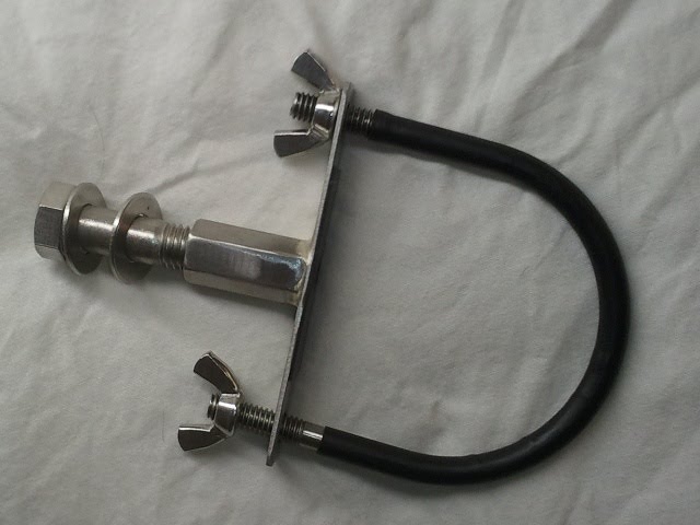
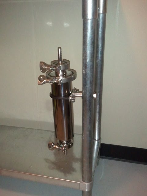
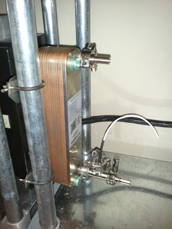
Making some good progress, finally ready to get back to brewing. I brazed up a triclamp temp probe for my BK (really my HLT but being used as a BK for now) and it is working great. The DS18B20 connected to some PTFE coated wire and potted inside with some heatsink compound.

You can click the pictures below for full size.


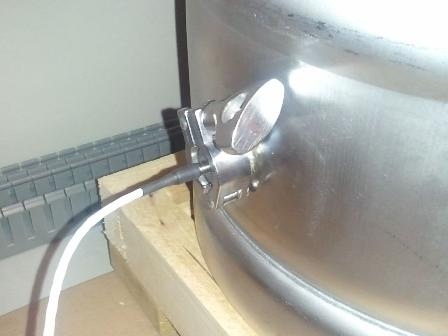
I haven't put it in an icebath or boiled it yet but it is keeping the same temps as my two other thermometers so I am not too concerned.

Last night I ran the system after working out some bugs the last few nights and I think it is ready to brew tonight, have 4 brews lined up for it this week.

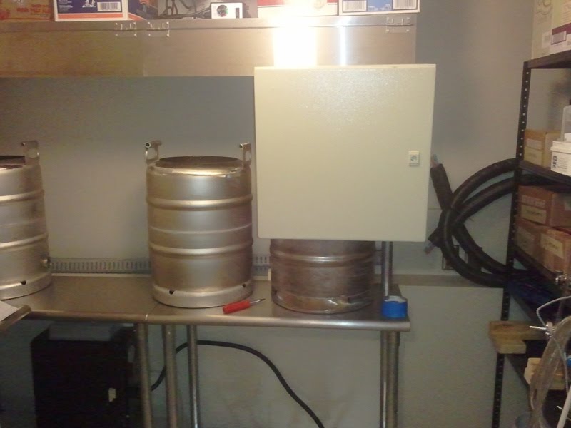
Here is the patched together setup, the power control box is pretty much done but the HMI is basically just a box covering a computer and a microcontroller.


Touch panel is working great, here is what the GUI looks like right now. There are a lot of debugging items shown that will be removed as the SW matures.


The PID loop needs to have some finer tuning, when set to 150 last night (or early this morning) it was able to stay between ~155 and 149.


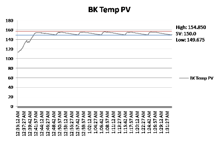
The controller needs to lead a bit as the water temp continues to rise for a few degrees even after the element turns off. Still, it wasn't half bad for a wild guess at the parameters.
 
Nice temp probe. Is it thermocouple based? What type of &#956;Controller are you using? Are all the GUI's developed in LV?

Sorry for all the questions but lovin this build!
 
Great progress!

I see you've got an autotune button in the preliminary GUI, how does the output of that correlate with your wild guess?
 
Is it thermocouple based? What type of &#956;Controller are you using? Are all the GUI's developed in LV?

All the answers are detailed in the thread but I will summarize: temp sensor is a DS18B20 1-wire, &#956;C is a LPC1768 via LPCXpresso board, the GUI is all LV with some custom indicators.

Great progress!

I see you've got an autotune button in the preliminary GUI, how does the output of that correlate with your wild guess?

I really haven't played around much with the PID control parameters yet. Tonight I am brewing an India Brown Ale and used the loop a bit for steeping the grains. Overall I just set the controller to 100% until it boils and then adjust it manually to achieve a nice strong rolling boil. Maybe this weekend I can work on tuning the controller, have a few more beers waiting to be brewed.
 
Quick update. Brewed four beers last week, trying to play catch-up for a long down time. My basement is finally bubbling away again. The dedicated room and equipment makes brewing a breeze compared to propane outside and cleaning up in the bathroom/kitchen.

new_brews1.jpg


Started working on the MLT. Added a 3/4" triclamp ferrule to the bottom for a drain and one to the side for a temp probe. Cut the majority of the upper skirt off leaving just the handles behind. It was easy enough that I think I will do the same on the BK and maybe the HLT. Here it is after being cleaned up with a flapper disk. At some point I think I might polish it up but that will have to wait for now.

MLT_cut_skirt1.jpg


Parts are beginning to roll in for my first attempt at a DIY peristaltic pump. I will post details on the build if it is even moderately successful...
 
Fantastic build, I don't know how I missed this until now.

It looks like you have background in PLC programming and software. I'm curious if you looked into skipping the HMI/any licensing fees and going with a pure C#/OPC based GUI?

Either way, Awesome work.
 
I like that idea of cutting off the upper skirt! What'd you use to trim it? Do they feel pretty sturdy still?

I stole the idea from this thread: How to lighten your sanke keggle

I used a 4-1/2" cutoff disk on my angle grinder, then followed up with a grinding of the weld and finished with a polishing with a 80grit flapper disk. All said and done it took a little over an hour from start to finish.

The handles are very solid, I don't know if you could carry around 15gals of water with them anymore but I don't intend to use them like that.
 
Fantastic build, I don't know how I missed this until now.

It looks like you have background in PLC programming and software. I'm curious if you looked into skipping the HMI/any licensing fees and going with a pure C#/OPC based GUI?

Either way, Awesome work.

Thanks! I'm an EE, well systems engineer, no PLC background but I do love embedded electronics and controls. I really only chose labview as it was available to me (work) and I know it decently well. I basically just build an executable that runs on the HMI machine.

Wow crazy. How much did all these parts cost?

A gentlemen never tells... actually I have the prices I paid for each item just not on a centralized list so I really have lost track of the total cost so far. Its best if I can't determine a total $ figure for both myself and SWMBO. Many parts have been scored from eBay so that has helped quite a bit.
 
Some of the pump parts rolled in this week, the majority coming from McMaster-Carr. I added some extra parts to the order to mount my Filter from Brewer's Hardware to my stand.

Used a u-bolt plate brazed to a coupling nut to mount the filter to a leg of one of my tables. Heatshrink tubing was applied the u-bolt and some rubber was attached to the plate to keep the filter in place. Overall, the outcome looks just like the model planned in 3D.

Mount:
filterMount1.jpg


Mounted to stand:
filterMounted1.jpg


3D Model:
FilterMount.PNG


The filter is nice and sturdy and with the addition of some wing nuts it will be really easy to remove at the end of each brew session to be cleaned. I also started working on the BK this weekend, still have a bit of work and some parts left to order for it to be complete.
 
Great work. I need some more intelligent friends.

My knowledge of Management and Professional Liability Insurance has not helped my brew rig in any shape or form

^^
what rmullis said except for the part about Management....Insurance, as I know nothing.

but holy moly! awesome that you appear to have as much interest in your job as hobby.

good luck. :mug:
 
^^
but holy moly! awesome that you appear to have as much interest in your job as hobby.

Now if only I could figure out a way for them to pay me to work on this...

Progress has been slow but steady, the pump idea is looking like it should pan out in one way or another. I cut my two other kegs to match the image I showed earlier. Almost all of the fittings for each keg have been brazed into place.

cut_kegs_and_hood.jpg


The shelf above the kegs is actually my vent hood. There are two flaps in the front (one is removed in this picture) that can be flipped up when I need to look into the kegs or add ingredients. The hinges have spring releases (scraps from work!) so they can be easily removed.


Received a bunch of connectors and parts over the last week so I began assembling some of the cable assemblies:

triclamp_tempprobe_cable.jpg


The Mini-XLR connectors allow the cable to be disconnected so the temperature probe can be cleaned or replaced if needed. The end of the cable is a standard RJ45 plug. I will be mounting a couple ethernet patch panels to the bottom of my control panel to connect all of the valves and sensors.

The HERMS tank and coil will hopefully be purchased after the holidays depending on the condition of my wallet. Once those are in place I should have everything I need plumbing-wise to put it all together.
 
Even though I understand 1 out of every 4 words, this thread gives me a huge goofy grin.

That gave me a grin. Had a good day in the brewery today, the HMI enclosure is mounted and looking solid.

HMI_arm_brewing.jpg


I used a $30 LCD swivel wall mount from Monoprice and replaced one of the legs of my table with a 5' 1-5/8 chainlink fence post. This swivel mount allows me to position the panel where needed for brewing or to place it out of the way so I can get to the shelves to the right.

HMI_arm_storage.jpg


Shot of the arm/back:
HMI_mounting_arm.jpg


And a top image of the setup in my model:
HMI_Mounted.PNG


I can now finish a bunch of the cables as I can measure the actual length needed before cutting them.
 
A lot has been going on since my last update. Purchased some of the last major items I need to get this system working like a false bottom, plate chiller, HERMS pot, pump motors/controls, and other various odds and ends.

Much of my work has been on the control panel and hopefully I will be able to post some pictures later when the parts are put back together. The last holes were drilled so it is ready for a test fitting/wiring.

I received a plate chiller from DudaDiesel and quickly got to work modifying for triclamps. The chiller ordered has 1/2"NPT males on each port so I drilled out a 3/4" triclamp cap to 1/2".

CFC_triclampDrilled.jpg


Next a small jig was rigged up to hold the fitting in place to be brazed. A washer inside the plate chiller provides tension to keep the fitting from moving.

PlateChiller_TriclampJig.jpg


After brazing both the wort in and out ports I performed a pressure test which went well and then mounted everything to my table.

PlateChiller_mounted.jpg


The short tee at the bottom has a temperature probe so I can monitor the wort out temp. I think I will order some 1/2" camlocks for the water connections.

More pictures to come as soon as the control panel is back together.
 

Latest posts

Back
Top