• Please visit and share your knowledge at our sister communities:
  • If you have not, please join our official Homebrewing Facebook Group!

    Homebrewing Facebook Group

Motorized Monster Mill Build

Homebrew Talk

Help Support Homebrew Talk:

This site may earn a commission from merchant affiliate links, including eBay, Amazon, and others.
I would say it's overkill personally. When you gear it down to a reasonable speed there's no way you'll need 1/2 HP. I guess the voltage is convenient though. The voltage may limit you if you ever wanted to put it on something else.
 
I would say it's overkill personally. When you gear it down to a reasonable speed there's no way you'll need 1/2 HP. I guess the voltage is convenient though. The voltage may limit you if you ever wanted to put it on something else.

Overkill is one thing...I just like the price :) I like the clean look of the gear reducer (which is awfully spendy in its own right) and notice that this motor runs a bit slower than the OP's motor. Not sure if that 200 RPM difference will have an effect after it is reduced?
 
Berrywise the rpm difference depends on how you plan on reducing it. I used a 1725 motor and a 10:1 reducer. That reducer would put you at 142 rpm might be too slow. Or you could go the pully route. Just my opinion. I over thought building my mill wayyy too much but looking back it was worth it.
 
1/2 hp is far from overkill..... My mill requires a 1 hp motor(MM3-2.0)

I have the MM-2, two six inch rollers. Will 1/2 hp be enough I guess is the question. Anyone have thoughts? I'm currently using a drill from harbor freight and just looking to clean up the look a little (yes I'm petty like that).
 

Berrywise, note that the listing is for a 50 Hz motor. If you're in North America, you probably have a 60 Hz power source.

A 50 Hz motor run on a 60 Hz supply will spin faster (20 %) and may heat up more. Probably not an issue in your use, but be sure to figure that in calculating your gear reduction or pulleys. If heat is a problem, you may be able to mitigate it with an additional fan and/or heat sinks or reducing your run time.

You can read more about it here:
http://www.engineering.com/ElectronicsDesign/ElectronicsDesignArticles/ArticleID/8154/Changing-an-Induction-Motors-Power-Supply-Frequency-Between-50-and-60Hz.aspx
 
Hello,

This thread has been wonderful in helping me add a motor to my MM3 Grainmill. However, I am struggling with the wiring of the reversing switch. Any help would be greatly appreciated.

I am using the same reversing switch as the Original Poster (from McMaster). And I am using this motor from surplus center: https://www.surpluscenter.com/Electrical/AC-Motors/AC-Motors-Face-Mount/1-HP-1800-RPM-115-230-VAC-56C-TEFC-LEESON-MOTOR-W-MANUAL-OVERLOAD-10-2706.axd

I have uploaded a pdf of the motor's wiring diagram to this post. Here is also a link to it: http://www.leeson.com/CnxDocRequest/PublishedPDF/grf_swd-0130015736_00500303_402810276_355.pdf

Thanks in advance for any help,

Bryan

View attachment M6C17FK80E Connections.pdf
 
Hello,

This thread has been wonderful in helping me add a motor to my MM3 Grainmill. However, I am struggling with the wiring of the reversing switch. Any help would be greatly appreciated.

I am using the same reversing switch as the Original Poster (from McMaster). And I am using this motor from surplus center: https://www.surpluscenter.com/Electrical/AC-Motors/AC-Motors-Face-Mount/1-HP-1800-RPM-115-230-VAC-56C-TEFC-LEESON-MOTOR-W-MANUAL-OVERLOAD-10-2706.axd

I have uploaded a pdf of the motor's wiring diagram to this post. Here is also a link to it: http://www.leeson.com/CnxDocRequest/PublishedPDF/grf_swd-0130015736_00500303_402810276_355.pdf

Thanks in advance for any help,

Bryan

I worked up this switch wiring diagram a while back for a Leeson motor. It's not using the OP's switch, but it might give you some ideas.

leeson-motor-grain-mill-wiring-64630.jpg


I don't have a diagram of the contacts for your switch.
 
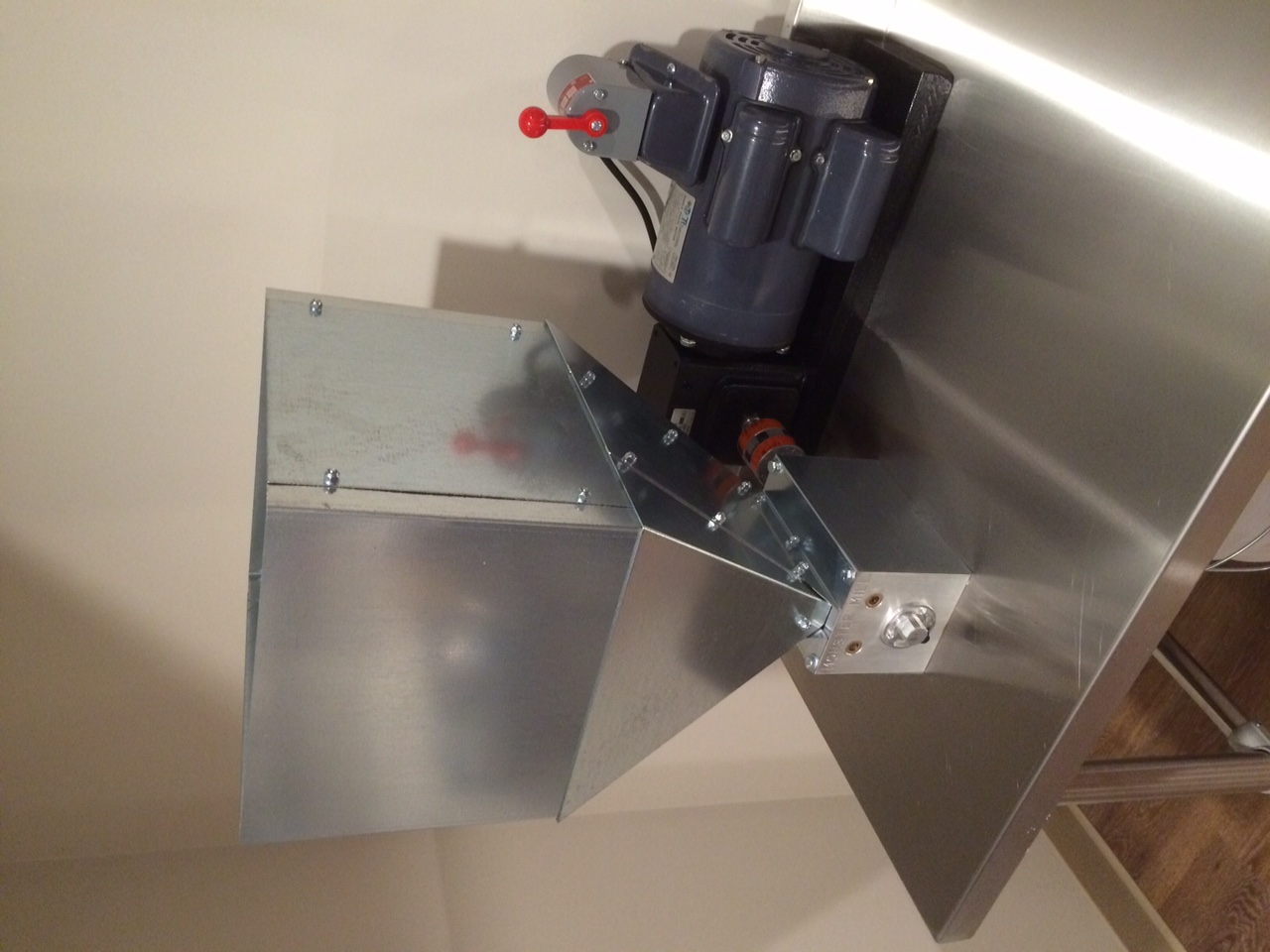
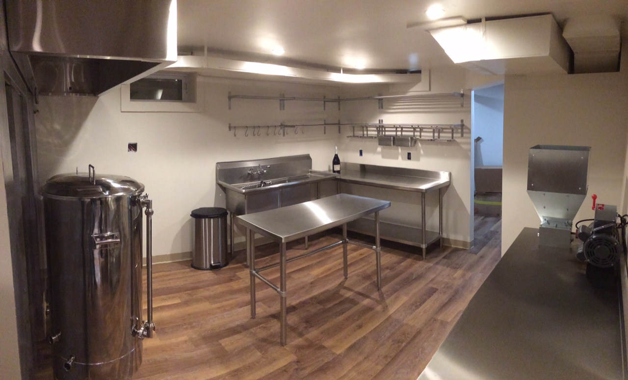
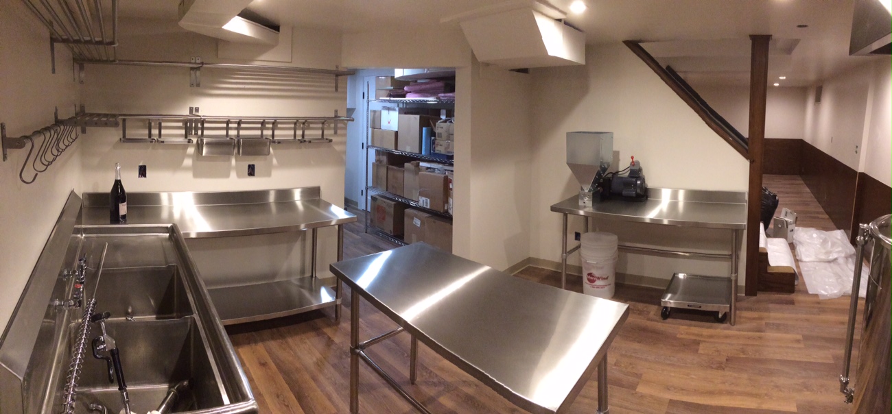
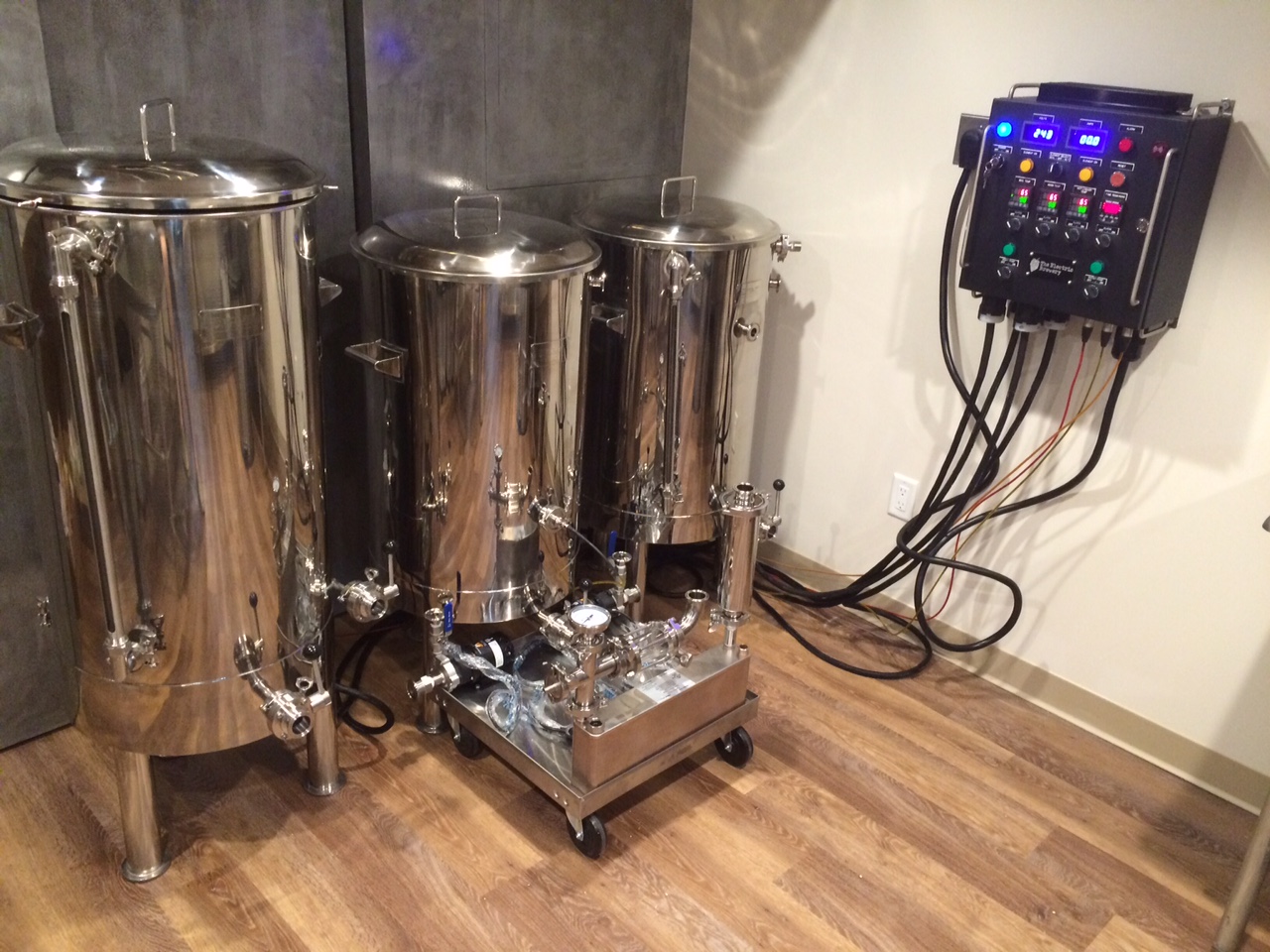
Ok ... so I moved from CA to NY, sold almost all my old equipment to my friend, had a clean slate, and decided to crank it up a notch! I'm building a new brewery with 1 BBL Stout tanks and an electric setup from theelectricbrewery.com. More than just buying the controller from Kal, his set-up also inspired me to use lots of pretty stainless steel (which is a lot cheaper these days) and build a new mill station in the progress.

My original set-up worked great, but there's always room for improvement:

Here's some notes on the build:
  • Mill and motor arrangement fit perfectly on table understructure. This wasn't planned. I just got lucky!
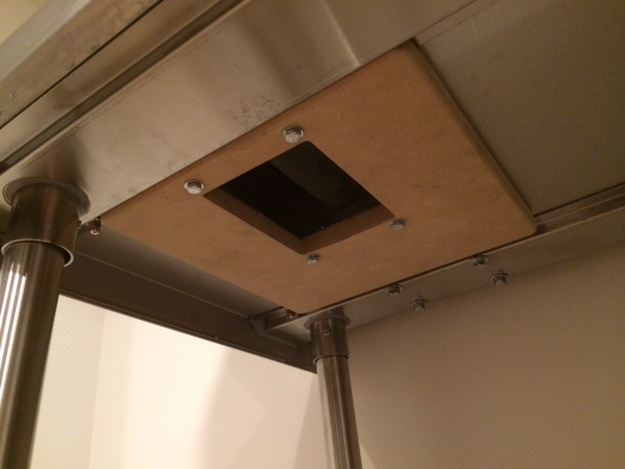
  • Monster now ships a thick MDF baseplate with their mill (sized to fit the top of a bucket I suspect). This is a needed addition. It's not as bad as a Barley Crusher, but Monster Mill rollers will pinch and jam if the base the mill is attached to isn't flat or flexes. This MDF board fixes that.
  • I attached the MDF board to the bottom of the table and bolted through it to the mill. It helps stiffen the thin steel table top and fits almost perfectly between the table structure rails (see photos).
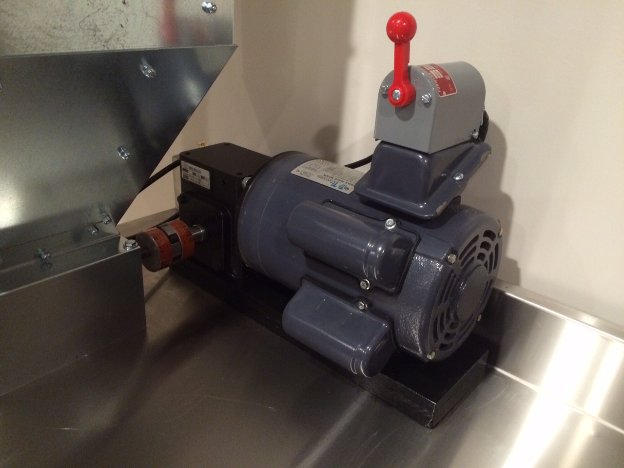
  • Motor doesn't have a base which was a little bit of an oversight on my part. I decided to instead mount off the gear reducer housing which worked just as fine.
  • Spacer to set height of gear reducer shaft to line up with mill shaft is hard wood (oak). Even though it's only attached through the bolts on the gear reducer housing, it extends under the motor to spread out the footprint on the table top to reduce bending. Also, if needed, I can wedge a spacer in between the wood and the motor if the motor bounces around too much (but it doesn't look like that will be a problem).
  • Bolts to bottom of gear reducer line up with edges of under table support rail which helps stiffen the motor mount (see photos). Again, I got lucky here and that wasn't planned.
  • For more usable table space and a cleaner look, I mounted the switch to the top of the motor electrical box.
  • Even though the motor was different than my first build, the wiring was almost exactly the same. The motor had the same color wires and T numbers. I did have to switch two wires to reverse the direction of the motor, but that was very easy to figure out based on the wiring info right on the side of the motor.
  • Although the stainless steel table looks super cool and was easier to buy than make, cutting through the thick gauge stainless steel top takes a little time (and I didn't want to screw it up!). To cut the rectangular hole for the grain, measure 4 or 5 times and cut once. I took it nice and slow with a Dremel and a tiny cut-off wheel. You could probably cut it faster with a hand grinder and cut-off wheel if you're steady handed. Drilling also requires patience. Start with a pilot hole, use cobalt steel bits, and use lots of lubricant or cooling fluid.

Enjoy!
 
Motor will work but expensive. Check ebay should find something around $130. My reducer doesn't have a base and I haven't had any issues. When you attach it to the motor and mill its not going anywhere.
 
Motor will work but expensive. Check ebay should find something around $130. My reducer doesn't have a base and I haven't had any issues. When you attach it to the motor and mill its not going anywhere.

Nothing in the $130 ball park has a base and face mount as well as being Cap start and 56C.

Understood about the base. Cheers!
 
You're right I didn't realize the price has went up in the last year. You're on the right track.
 
About to finish sourcing my similar build and struggled to find a well priced 1HP Motor with these specs: 56C, Cap Start, Base and Face Mounting - Alas I found this:


http://www.surpluscenter.com/Electr...115-230-VAC-56C-TEFC-LEESON-MOTOR-10-2700.axd


Also, this BASE for the 10:1 Speed reducer looks like it might make mounting it a bit easier. Thoughts?


https://www.surpluscenter.com/Power...SE-FOR-175-FRAME-GEAR-REDUCER-13-175-BASE.axd


The base will help spread the load of the motor if you're going to hang it off the gear reducer. However, you'll still need another spacer under that one (~3/4" thick) to raise the shaft of the gear reducer to line up with the shaft on the mill.
 
The base will help spread the load of the motor if you're going to hang it off the gear reducer. However, you'll still need another spacer under that one (~3/4" thick) to raise the shaft of the gear reducer to line up with the shaft on the mill.
 
Drunkenmonkey, that is a very nice brewery! I have pretty much the exact same stuff only a smaller 20 gallon system. Where did you get the stainless steel rollers to mount your chiller, pumps, strainer and oxy system?
 
The base will help spread the load of the motor if you're going to hang it off the gear reducer. However, you'll still need another spacer under that one (~3/4" thick) to raise the shaft of the gear reducer to line up with the shaft on the mill.

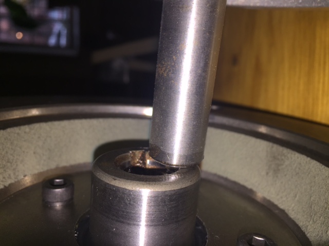
Drunkenmonk, my good man. Quick question. I have attached 2 photos. The show the height difference between 1) the Motor (leeson with base) and the speed reducer and 2) the speed reducer and mill.

Is there an EXACT hight difference that would allow me to go buy corresponding blocks to put under the motor and under the reducer?

The difference between motor and reducer seems to be maybe 1/2" and the difference between the reducer and the mill seems to be 1 1/2" - does this make sense? I would hate to have the blocks JUST be off.

IMG_4172.JPG


IMG_4169.JPG
 
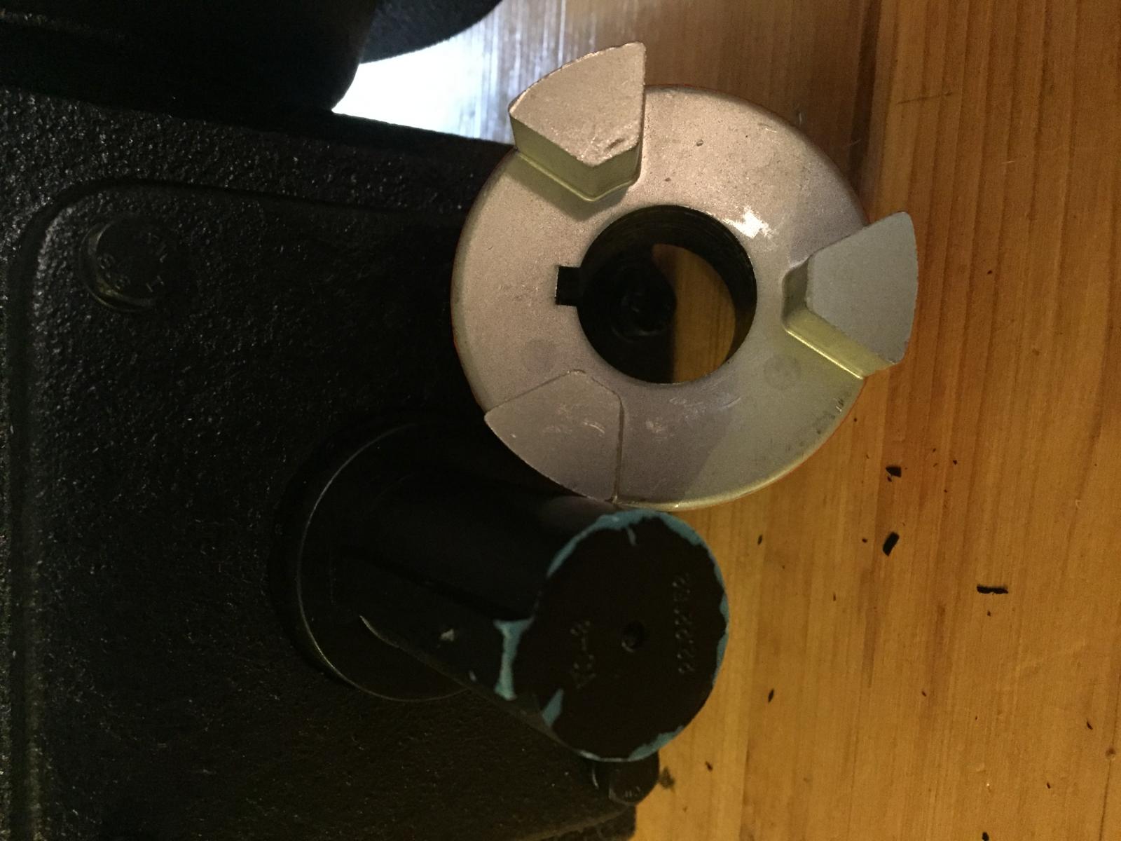
Can't help with the blocks but the 10:1 reducer should list the output shaft size. I had an issue with mines as well and if i can remember correctly the reducer might come with two different key sizes for the coupler. Recheck the box i remember this was a pia but turned out to be simple.
 
Here's some photos:

Can you explain the two pieces of wood under the bottom that hold the bucket? -Did you make or buy them? If buy; what exactly are they and where can I get them?

(Obviously I'm not very handy.)

I'm currently building my cart and I LOVE this simple solution for avoiding dust.

-I was thinking about buying a gamma lid and just cutting it and screwing it to the bottom of mine and then screwing the bucket in but that's a lot more complicated, slow and a bit more expensive than your "rails" solution.


Adam
 
Back
Top