Motorized Grain Mills: Time to show them off!

Homebrew Talk - Beer, Wine, Mead, & Cider Brewing Discussion Forum

Help Support Homebrew Talk - Beer, Wine, Mead, & Cider Brewing Discussion Forum:

This site may earn a commission from merchant affiliate links, including eBay, Amazon, and others.
I need a little assistance here. I am reading that there is alot of concern about torque and the requirement to crush grains. I also see alot using 1/2hp motors running pulleys, if using the formula of torque = hp. × 5,252 ÷ rpm : then a 1/2 hp motor at 1750 rpm is only 1.5 ft lbs, yet i do not see very many stating that they are running into problems. am i missing something here, or is the torque concern only for direct drive units?
 
I need a little assistance here. I am reading that there is alot of concern about torque and the requirement to crush grains. I also see alot using 1/2hp motors running pulleys, if using the formula of torque = hp. × 5,252 ÷ rpm : then a 1/2 hp motor at 1750 rpm is only 1.5 ft lbs, yet i do not see very many stating that they are running into problems. am i missing something here, or is the torque concern only for direct drive units?

You need to use the RPM of the shaft on the mill. My 1/2 HP American ale works motors are geared down to either 180 or 240 rpm (depending on which option you choose).
 
so RPM on the mill side after gearing will be roughly 192, putting my torque to about 13.5 or so ft/lbs. but I see people on here saying they feel the need to get up higher, but almost every motorized mill I have seen at any homebrew store use 1/2 hp motors with no issues (or at least no issues I have witnessed that is)
 
so RPM on the mill side after gearing will be roughly 192, putting my torque to about 13.5 or so ft/lbs. but I see people on here saying they feel the need to get up higher, but almost every motorized mill I have seen at any homebrew store use 1/2 hp motors with no issues (or at least no issues I have witnessed that is)

BUT, if I swap out this 1/2hp motor to a 2hp motor (which seems to be physically the same size) and only about a $30 difference, I can jump from 13.5 ft/lbs to 52 ft/lbs...which seems to go along with what others on here are saying, but I just feel that a 2hp motor is WAY overkill.
 
so RPM on the mill side after gearing will be roughly 192, putting my torque to about 13.5 or so ft/lbs. but I see people on here saying they feel the need to get up higher, but almost every motorized mill I have seen at any homebrew store use 1/2 hp motors with no issues (or at least no issues I have witnessed that is)

I use a 1/2 HP motor geared down to 180 rpm with a 3 roller mill and I have never experienced a lack of torque. The shaft diameter on my motor is 22 mm and I would say that that motor is overkill. I cannot speak for other brands of motors.
 
BUT, if I swap out this 1/2hp motor to a 2hp motor (which seems to be physically the same size) and only about a $30 difference, I can jump from 13.5 ft/lbs to 52 ft/lbs...which seems to go along with what others on here are saying, but I just feel that a 2hp motor is WAY overkill.

You also need to consider the amp draw and voltage required (120V vs 240V) when going from a 1/2 HP motor to a 2 HP motor which may increase your $30 difference taken into account the cost for wiring.
I feel that my 1/2 HP motor is way overkill.
 
I use an old 1/4 HP motor, geared down 8:1 with pulleys, for a little over 200 RPM on the rollers. Never had a problem with power. I think 1/2 HP will be plenty.

Mill_02.jpg
 
Yeah, i think so too, now if i can just figure out a good tensioning device

If you look at my picture above, the motor is mounted on a small piece of 1/2" plywood, which is in turn attached to the 3/4" plywood base. It's not easy to see in the pic, but there's about 1/4" space between the motor mount piece and the base. I use 4 screws to force the motor mount piece downward. I can adjust the screws until the belt is sufficiently tight. If I want to remove the motor or belt I just unscrew the mount and lift the motor upward.
 
BUT, if I swap out this 1/2hp motor to a 2hp motor (which seems to be physically the same size) and only about a $30 difference, I can jump from 13.5 ft/lbs to 52 ft/lbs...which seems to go along with what others on here are saying, but I just feel that a 2hp motor is WAY overkill.
13.5 ft/lbs = 162 in/lbs which is more than enough. Most mills I have seen run great with 45-50 in/lbs. My mill has lot less toque.
For my 52 gallon mashtun I use a 180 in/lbs motor for the mixer.
 
Finally pulled the trigger and purchased the Williams Brewing mill motorizing kit. No regrets, but my setup took a bit more work than anticipated. The motor only turns clockwise, and my mill only turns counter-clockwise with no way to reverse the drive roller. So I was going to buy a new mill until I realized I could flip the mill and mount everything beneath the deck, which put the drive roller in correct orientation to pull the grain though the mill. Just had to find a new way to mount the hopper above the deck.....

After several hours of tinkering I realized I could build all of this into my work table, and I could not be more pleased with the results. Now have full use of work top, and for the 5 minutes per brew day when the mill is needed just pop the cover, insert hopper, put the bucket underneath and press the button! Take it apart and store everything under the deck until next brew day.

The Williams kit includes a great little motor and everything you need except for a couple of metric allen wrenches to tighten it up.. Seems to have plenty of torque for my little mill and cranked through 12 lbs of grain in no time.

IMG_20180422_100547.jpg
IMG_20180422_100600.jpg
IMG_20180422_100621.jpg
 
Last edited:
IMG_0720 (1).jpg
I was out the other day and spotted this crusher.

It has a 100hp motor and stands over 12ft tall.

The feed mill is being torn down.

I guess this crusher is just too big to move to the scrap heap.

Anyway I thought it interesting to see.

Enjoy
Cabin
 
According to the diagram the motor is bi-directional.

I tried reversing the supply wires to no avail, and asked williams support. Was told it cant be reversed, that it is hard wired for their mill. Perhaps it is the wires between the switch and the motor that need to be reversed?

At any rate, the bottom mount provided a more elegant solution so it was a good problem even if only due to my cluelessness.
I think it likely that it is the reduction gear that can't operate in reverse. If you succeed in reversing your motor you might damage the gearing. Besides, the issue lead you to a clean, clever solution. Well done!
 
It’s not much, but I built this and it is mine. For the inquiring individual:
- Monster Mill MM2.0, 3/8” drive, 1.5” wheels
- Dayton 1/4 hp gear motor, 60 rpm and 300 in-lb output
- McMaster Carr spider coupling, 3/4” x 3/8”
- IKEA Table top and legs
- Scrap wood for shimming the mill, 1.5” x 2” lengths
- Scrap wood for racking the bucket, 3/4” + 1/2” lengths

Looking forward to taking a first crack at it this weekend!
IMG_1527780264.885660.jpg
IMG_1527780274.852800.jpg
 
Just finished my first attempt at motorising my little mill.

I took an old 12v gate motor that a friend gave me that runs at 3000rpm and 3D printed a herringbone gear train to bring it down to about 250rpm.
Ran through 5kg of grain tonight and the motor doesn't even hesitate when the grain is added.

SmartSelect_20180601-231630_Gallery.jpeg
 
Just finished my first attempt at motorising my little mill.

I took an old 12v gate motor that a friend gave me that runs at 3000rpm and 3D printed a herringbone gear train to bring it down to about 250rpm.
Ran through 5kg of grain tonight and the motor doesn't even hesitate when the grain is added.

View attachment 573115
Thats pretty darn neet.

I suppose it's too early to see if the geartrain will stand up to hard-use.. I'd sure like to know how it does over time...

did you put bearings on the main-shaft/etc.. it looks like it, but hard to see in the pic
 
Yes all shafts are on bearings. That picture is version 1, when I get a chance I will take a photo of version 2 where I have combined the the bearing blocks into one piece.

As I said the gears survived the first 5kg (11pounds) just fine with no sign of any stress.
I will keep an eye on them, but if they do break it costs me nothing to reprint them. I can always make them wider to distribute the forces (might only need that on the final drive gears as they take the largest torque). I chose herringbone gears because it they have the strength advantage of helical gears (more teeth engaged at any point in time) but they do not impose sideward forces like helical gears do.
 
Just finished my first attempt at motorising my little mill.

I took an old 12v gate motor that a friend gave me that runs at 3000rpm and 3D printed a herringbone gear train to bring it down to about 250rpm.
Ran through 5kg of grain tonight and the motor doesn't even hesitate when the grain is added.

View attachment 573115
What do you use to power it? I would figure it draws a few amps to run. I have a lot of 12 volt stuff and I haven't been able to find an inexpensive power supply to power my stuff, so I just use a car battery.
 
What do you use to power it? I would figure it draws a few amps to run. I have a lot of 12 volt stuff and I haven't been able to find an inexpensive power supply to power my stuff, so I just use a car battery.
I am using a simple 12v psu I bought at the local Chinese market that is used to drive LED lights. It is rated at 120w so it will supply 10A . For a test I initially used my lab power supply which will drop the voltage when current reaches the Max of 6A, I never saw the overload light come on on my power supply so it is definitely using less than 6A.

Next time I will hook up an ammeter and see what my current drain is.
I will habe to look into that, I can't see anything I'm using to pull even that many amps, thanks for the info.
 
15284115594451512146576617787433.jpg


Mines not attached to a bench yet but it is finished and works great..

Only thing I might add is a detachable hopper extension...right now I can get almost 10 pounds of grain in the hopper at a time.

Everything is oak and finished with some oak stain and poly sealer.
 
Thats pretty darn neet.

I suppose it's too early to see if the geartrain will stand up to hard-use.. I'd sure like to know how it does over time...

did you put bearings on the main-shaft/etc.. it looks like it, but hard to see in the pic
As promised clearer photos here.

The red gears are new not because the blue ones broke but because I wanted to make sone minor sizing changes to them and I was out of blue filament to print with.

If anyone wants gears made I am happy to share the files and they can get them printed locally, just PM me.

20180606_201631.jpeg
20180606_201625.jpeg
 
157RPM 3 Roller Mill

The old motor I had laying around the shop had a little air compressor attached to it...I don't have the tank anymore, but after a few seconds of pressure build up in the hose, it will release a descent puff of air.

IMG_0896.jpg

 
I love that! Steam-Punk grain mill! :D

As for the edging, I went to the local paper/craft store and picked up a couple of plastic binders for school reports.
35-460-460.jpg

I mitered the corners then simply slipped them over the edge. It has lasted for years...

grain_mill_station_08_sm.jpg


Cheers!
 
I tried reversing the supply wires to no avail, and asked williams support. Was told it cant be reversed, that it is hard wired for their mill. Perhaps it is the wires between the switch and the motor that need to be reversed?

At any rate, the bottom mount provided a more elegant solution so it was a good problem even if only due to my cluelessness.

As the OP cleverly sorted out how to make the stock rotation work, this is really just informational for anyone else who wants to make the alteration.

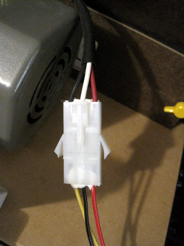
The gearmotor sold by Williams (and now MoreBeer too) does indeed reverse and seems to operate fine in either direction (don't know if there is a torque reduction for one or the other tho), however the color codes on the nameplate don't match what's inside the provided switch box as their harness changes wire colors at the coupling, which could cause some confusion. The reverse rotation change is as simple as moving the one mains line from one side of the capacitor to the other, and leaving the other connections as-is. (Red is common, Black/White is the capacitor pair)
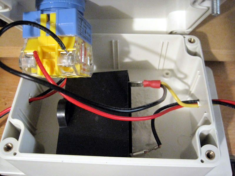
I reset mine to run CW as such:
W_wire1.JPG

W_wire2.JPG

Those are F1 spade connectors on the cap, I had to replace one to make the new connection.
Not sure why Williams support was being difficult on this matter - perhaps they were just avoiding some perceived liability issue with the end user altering electrical components? (shrug)
I never found any detailed specs for this Kebang motor, so no idea what the torque actually provided is other than the '90 Watt' label. The output at 60Hz is ~216RPM, doing the math from nameplate 50Hz@1350 = 60Hz@1620 / 7.5 gearbox.


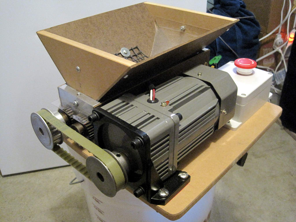
I added one of these to my JSP mill this year, though perhaps in an odd way compared to most others here:
W_JSP.JPG

The idea was to keep the system compact and portable by mounting to the stock base with a parallel arrangement using pulleys. (timing belt & pulleys from McMaster) The only assembly issue I ran into was this motor has a 12mm shaft and the mill is 3/8"... and timing belt pulleys don't seem to come in mixed metric/english bore sizes for a given belt type, so extra work with shims to 1/2" was required.
Works so far, no stalls or skipping so the torque must at least be adequate. Now that the motor and layout are proven to work I plan to change the base plate to a larger real wood build - the MDF flexes alarmingly when under load (pulls on the top, so has some meaningful leverage), and arrange a guard/cover.


Sadly, I found out recently that the JSP mill is no more. I was looking into one for one of the friends who taught me brewing in the first place, and Jack wrote back that his shop burned earlier this year and there there is no plan to resume production. Darn shame, as I quite like the mill with it's gear drive option.
-KD
 
Yes all shafts are on bearings. That picture is version 1, when I get a chance I will take a photo of version 2 where I have combined the the bearing blocks into one piece.

As I said the gears survived the first 5kg (11pounds) just fine with no sign of any stress.
I will keep an eye on them, but if they do break it costs me nothing to reprint them. I can always make them wider to distribute the forces (might only need that on the final drive gears as they take the largest torque). I chose herringbone gears because it they have the strength advantage of helical gears (more teeth engaged at any point in time) but they do not impose sideward forces like helical gears do.

Which engineering software did you use to create the gears? I’m loving this idea of yours. Thanks for sharing.
 
I have used solidworks. Happy to share the files I found the original on the net and adapted for myself. Honestly can't remember where I got the original though.
They are done so that you can just enter dimensions into the variables fields to change width, teeth etc. The ganged gears I did using an assembly of two seperate gears to create one stl file.
 
Last edited:
Back
Top