• Please visit and share your knowledge at our sister communities:
  • If you have not, please join our official Homebrewing Facebook Group!

    Homebrewing Facebook Group

Manual vs electronically controlled heating elements

Homebrew Talk

Help Support Homebrew Talk:

This site may earn a commission from merchant affiliate links, including eBay, Amazon, and others.
The contactors allow you to switch both of the high current 240V lines and also turn the power off to both elements. This can also be done with a high current double pole - double throw - center off switch.

With the PID powered off, a voltage can still be presented to the elements.
 
understood, i think...

So the contactor is a safety device to allow the user to cut power to the elements. And, you put a manual switch on the contactor because you does not want the SSR to be continually switching the contactor because they are not designed to be cycled every other second? (else why not just let the SSR cycle the contactor - or the PID for that matter).

So, if i wanted to run a duel PID system i could use basically the same diagram provided above except i would need two SPDT contactors (once for each element) verses one DPDT. This would allow me to run both elements at the same time if needed. (i will likely have a 50amp dedicated circuit as my brew rig is about 10 feet from my breaker box).

what i don't understand is that it looks like whenever the contactor is closed (on) the elements will be getting power from line 1 and they already have a ground connections. Does that mean even when the PID says to turn the element off that the element is still heating at 110v (25%)? Or, am i just confused?
 
Yes. (you are confused) With the SSR in place, it controls one leg of the 240V power. When the SSR is switched off by the PID the circuit to the element is effectively open and no current flows. Yes there is 120V applied to one of the element terminals, however, there is no path for current to flow through the element. If you were to touch either of the terminals on the element, you would risk your life.
 
To your first comment - exactly as I understand it (from reading my PID manual and from Walker's comments). Contactors aren't supposed to cycle on and off like that so... the contactor is after the SSR in the wiring. your switch closes the contactor with lower voltage and amperage than the referenced toggle switch. Therefore your contactor is always on (not cycling), when you switch it on; the SSR does the cycling sending current through a constantly closed contactor.

PJ - please correct my on this if I am mistaken, but the way I understood it was:
1. SSR's can fail in the "on" or closed condition.
2. Contactors fail in the "off" or open condition.
 
You can read more about why this is a good idea on my heating element wiring page here, especially the "How it Works" section: http://www.theelectricbrewery.com/control-panel-part-2?page=13

To quote myself (I included extra surrounding information for context):

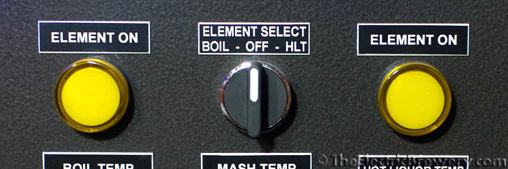
We control which of the two heating elements may be active with the ELEMENT SELECT 3 position switch. It has 3 settings: BOIL, OFF, or HLT. The OFF setting is purposely placed in between the other two to ensure that the one element is truly off before the other is turned on. The ELEMENT SELECT switch does not turn on the respective element, it only allows the element to be on if the PID controller/SSR wants it to be on. In other words, the PID controller may be firing the SSR but unless the ELEMENT SELECT switch is also set correctly the element will not receive any power.

Two ELEMENT ON 220V pilot lights are used to let us know when power is being applied to one of the two heating elements. This is an added safety precaution to show us what is going on.

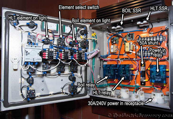
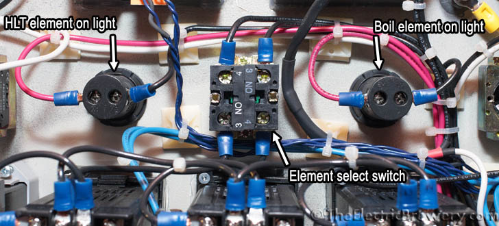
The ELEMENT SELECT 3 position switch is used to control which (if any) of the two kettles can receive power. The ELEMENT ON 220V pilot lights show us when a heating element is firing.
IMG_6803.jpg


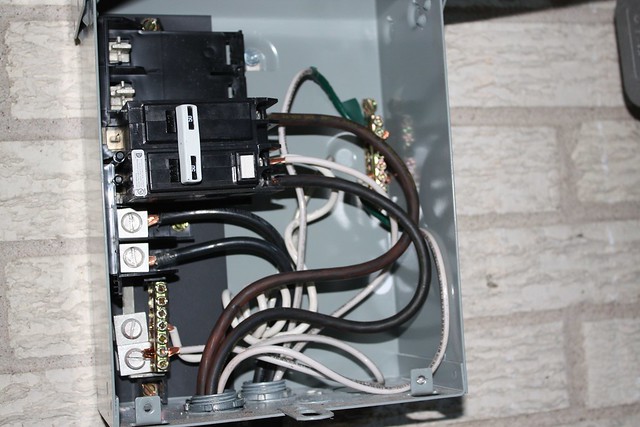
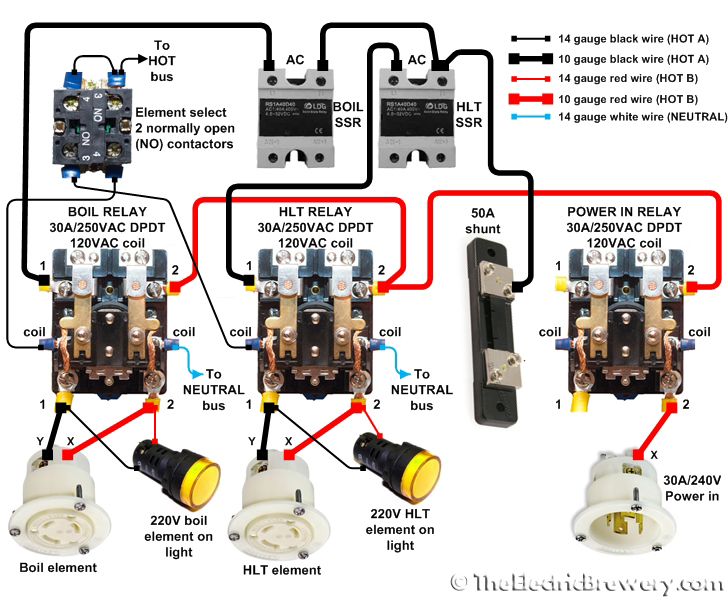
Wire up the components as shown in the diagram below using the wire sizes and colours indicated.

Heating element wiring diagram:
elements.jpg


How it works

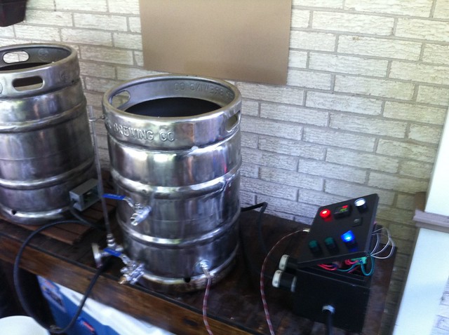
The Boil Kettle and Hot Liquor Tank heating elements are fed from the 120V HOT A and HOT B lines for a total (differential actually) of 240V.

When the ELEMENT SELECT 3 position switch is turned to either BOIL or HLT, the switch energizes either the BOIL or HLT relay coil which in turn allows power to pass only to that one heating element regardless of how the PID controllers are set.

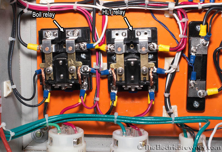
At first glance the BOIL and HLT relays may seem redundant: We use a PID which controls an SSR which in turn tells the element when to fire. So why are the mechanical relays needed at all? Why don't we simply use the ELEMENT SELECT 3 position switch between the PIDs and SSRs instead? The reason is safety: The mechanical relays ensure that there is a complete physical disconnect between both HOT lines and the heating elements when the relay is off. This is important as we will often be working or cleaning one kettle while the other is operational.

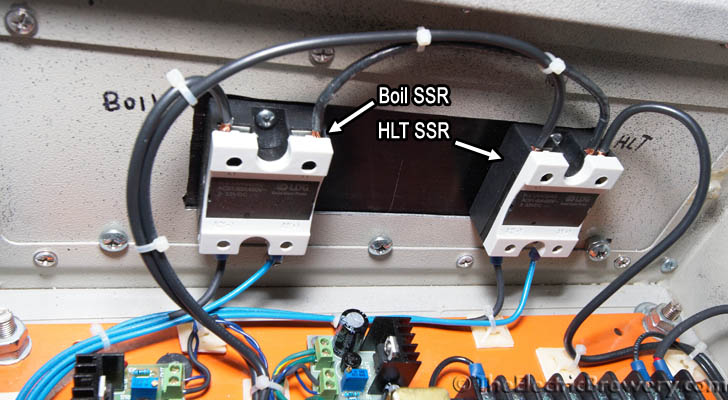
Doing something similar with SSRs would require 2 SSRs per heating element (one for HOT A and one for HOT B), but even that would not be 100% safe as SSRs have a small amount leakage current that flows through at all times, even when the SSR is off. SSRs are also known to fail from time to time and when they do, they tend to fail "closed" meaning that heating element stays on. The mechanical relays provide us with the piece of mind that when we've turned the element off, there is no possibility of it coming on by accident nor is any side of it energized.

So why use SSRs at all? Why can't we just use the mechanical relays? SSRs are Solid State Relays, essentially switches with no moving parts so they are able to switch as fast as required, often many times per second. Regular mechanical relays are not meant for this amount of switching as the contacts would wear out quickly. Whenever frequent switching is required, SSRs are used instead as we've done here. The three 30A/240V DPDT relays we use are only switched once or twice during the brewing session so they are being used in the way that they are designed to operate.

Whenever power flows to one of the heating elements, the respective ELEMENT ON 220V pilot light (wired in parallel with the element) turns on letting us know that power is being applied. This is an added safety precaution to show us what is going on. The PID controller may be firing the SSR, but unless the respective mechanical relay is also on the ELEMENT ON 220V pilot light will not come on.

IMG_6681_letters_elements.jpg


IMG_6690_letters.jpg


IMG_6716_letters.jpg


IMG_6979_letters.jpg

Kal
 
To your first comment - exactly as I understand it (from reading my PID manual and from Walker's comments). Contactors aren't supposed to cycle on and off like that so... the contactor is after the SSR in the wiring. your switch closes the contactor with lower voltage and amperage than the referenced toggle switch. Therefore your contactor is always on (not cycling), when you switch it on; the SSR does the cycling sending current through a constantly closed contactor.

PJ - please correct my on this if I am mistaken, but the way I understood it was:
1. SSR's can fail in the "on" or closed condition.
2. Contactors fail in the "off" or open condition.
That is exactly right.
 
SSRs have leakage current too - even when 'off', an SSR will let some current through.

Kal
 
Kal - thanks for that information - this makes perfect sense why EE's and other electrical savvy folks were so adamant about using something to control current flow AFTER the SSR. I had thought it was just to protect against a failed SSR in the closed condition. In actuality it protects from leakage flow too (happens more often than a failed SSR scenario). This is a must have safety feature IMO (whether toggle switch or contactor, etc.)
 
This is a must have safety feature IMO (whether toggle switch or contactor, etc.)
Agreed. That's why I do it this way.

Some go a step further and use two SSRs to cut off [most of] both sides of the element when it's not firing but I don't really see how that adds any safety since when the system's up and running the element will be firing every few seconds most likely. It's not like you're going to stick your hand in there in between cycles!

You should only stick your fingers in there when you've switched off the output to the element using a physical switch that controls a mechanical contactor/relay.

In an ideal world, the control panel should be completely off before putting your hands in anywhere but I like to sponge down my HLT while my boil is ramping up so having that contactor/relay that physically disconnect the element gives me the piece of mind I need.

When I clean out the boil kettle the control panel is usually completely off.

Kal
 
Kal and P-J:

Thanks for setting me straight. I forgot that there is no ground/neutral on the elements - only hot1 and hot2. It now makes sense that the element only fires when hot1 and hot2 are both live to complete the circuit.
 
The contactors allow you to switch both of the high current 240V lines and also turn the power off to both elements. This can also be done with a high current double pole - double throw - center off switch.

With the PID powered off, a voltage can still be presented to the elements.

So now I'm confused a little bit.

In this setup either a DPDT switch or contactor with a selector switch is used to allow power to the element but no power is sent to the element or to the PID until the push switch is activated and the circuit is closed. Am I misunderstanding this? If either were open no power would get to the element.

The main benefit of a contactor over a DPDT switch is that the actual switch will have 120 running to it, not 240. Wouldn't a plastic, or any non-metal, DPDT switch eliminate any risk of currently potentially running through the user? As far as leakage current I suppose it is a nice benefit, but in this application I can't imagine cleaning the kettle without disconnecting the elements/probes from the control panel, not just turning it off, but maybe this is just me being overly cautious.
 
Tony,
The purpose of the contactors or the DPDT switch is to isolate the element (kettle) from the power source. Simply - That is all it is.
 
Kal - thanks for that information - this makes perfect sense why EE's and other electrical savvy folks were so adamant about using something to control current flow AFTER the SSR. I had thought it was just to protect against a failed SSR in the closed condition. In actuality it protects from leakage flow too (happens more often than a failed SSR scenario). This is a must have safety feature IMO (whether toggle switch or contactor, etc.)

Actually, there's no safety aspect to this. The leakage current through the SSR has nothing to do with the suggestion to put the contactor after the SSR. Even if you had the contactor in front of the SSR (which is actually how I have mine set-up), if the contactor is off, there is nothing available to leak through the SSR.


The reason it was suggested to put the contactor after the SSR was solely based on your costs. If you had put the contactor in front of the SSR, then you would have needed two SSRs in your system. Your selector would direct power towards one element or the other, but you would then need to put SSR control both of those paths (one SSR for BK and another for HLT).

By putting SSR control before the point where power was directed one way or antoher, you were able to design with just a single SSR.

Understood and agreed. The "AFTER" was a memory recall issue - my bad.

Walker - Remember when we talked about the PID wearing out the contactor (post #308 on my build)? Basically I read the manual and it says essentially, not to have the PID wired to turn on and off a contactor or relay that would allow the feed power to the SSR. If you did you would hear the contactor click clacking every time the PID turned the power on the contactor (wearing out the contactor) so basically liek you said, you need to wire it on a switch so the contactor is closed constantly and the SSR does the cycling (Before or after).

However there still is a safety aspect to the contactor, if wired as described. The key being.... it can be BEFORE or AFTER the SSR. Case in point - it isolate the elements, in either location, from current leakage.

EDIT:

Should also say - thanks again man - the electric rig you helped me with rocks. Put the reflectix on it and plan to brew this sat. Control panel is kicking arse. Now I just need a brewstand - for now, folding banquet table....
 
Walker - Remember when we talked about the PID wearing out the contactor (post #308 on my build)? Basically I read the manual and it says essentially, not to have the PID wired to turn on and off a contactor or relay that would allow the feed power to the SSR. If you did you would hear the contactor click clacking every time the PID turned the power on the contactor (wearing out the contactor) so basically liek you said, you need to wire it on a switch so the contactor is closed constantly and the SSR does the cycling (Before or after).

That's a completely different issue. You don't want the PID to control the contactor for sure. The PID should always control the SSR. Whether you put the contactor between the SSR and the element or between the incoming power feed and the SSR is irrelevant for the most part.

Should also say - thanks again man - the electric rig you helped me with rocks. Put the reflectix on it and plan to brew this sat. Control panel is kicking arse. Now I just need a brewstand - for now, folding banquet table....

You're welcome to my help.

Please don't take this the wrong way, man, but I don't think you're really ready to be giving a lot of advice on electric brewing systems at this point. When people come on here and ask questions, and you answer, they are going to listen to you intently, assuming you know very well what you are talking about. If you are not 100% certain something, don't answer. Incorrect information and assumptions are worse than no information at all when it comes to things that can be lethal if done incorrectly.

Sorry. Not trying to pick on you or anything. I just get REALLY scared and REALLY nervous with people on these electric threads.

I've gotten nervous enough about it recently that I am no longer offering advice or assistance with electric system builds except for guys here locally in NC that I can sit with and talk to face-to-face.
 
That's a completely different issue. You don't want the PID to control the contactor for sure. The PID should always control the SSR. Whether you put the contactor between the SSR and the element or between the incoming power feed and the SSR is irrelevant for the most part.


You're welcome to my help.

Please don't take this the wrong way, man, but I don't think you're really ready to be giving a lot of advice on electric brewing systems at this point. When people come on here and ask questions, and you answer, they are going to listen to you intently, assuming you know very well what you are talking about. If you are not 100% certain something, don't answer. Incorrect information and assumptions are worse than no information at all when it comes to things that can be lethal if done incorrectly.

Sorry. Not trying to pick on you or anything. I just get REALLY scared and REALLY nervous with people on these electric threads.

I've gotten nervous enough about it recently that I am no longer offering advice or assistance with electric system builds except for guys here locally in NC that I can sit with and talk to face-to-face.

I respect your perspective and since you prefer me not to respond - consider me counted out.

What I said about the contactor was not unsafe no matter how you wired it (before or after) - but it was misinformation none-the-less, from a mis-recollection on my part. When I wasn't sure of something I said so, and specifically asked P-J or Kal to confirm it.

No sweat though man - point taken - I am off the ebuild threads.

Good luck with your build gents.
 
So after a month of research and acquiring parts I just finished my wiring last night. The problem is, once I plugged it in the GFCI breaker (50A spa panel to a 50A dedicated breaker) tripped. When I applied power the "power in" light flashed for a split second and then the breaker tripped. After removing the power to the "power in" light the panel was plugged in again, but the breaker did not trip until I pressed a switch, then the light flashed for a second and the breaker tripped. I have tried this with and without loads attached, which leads me to think that the problem is with the switches.

For the switches I used these with brown NO blocks and wired them as so

Power - Terminal #4
Load - Terminal #3
Load jumpered - X2
Neutral - X1

I've checked all of the wiring, gone over everything with a multimeter to unsure nothing was shorting out, even had my electrical engineer wife do the same. No issues found. The wiring diagram I used is:

Auberin-wiring1-a4-4500w-30a.jpg


Any thoughts on what might be causing the breaker to trip? I've never used these switches before so hopefully I am just missing something. Thanks guys.
 
It almost sounds like you have wired the ground to X1 instead of the neutral. As soon as the lamp trys to illuminate the GFCI trips with the leakage current. As a test, disconnecting all of the switch X1 connections and try it again.

Please let me know.
 
After mulling this over a little more, there is another possibility. It's possible that you do not have the neutral wired correctly in the spa panel. The neutral and the ground must be independently wired and the output neutral must come from the GFCI breaker.
(If you are using a 3 wire input to the spa panel, I can show that wiring as well.)
The panel should be wired like this:

power-panel-5.jpg
 
Thanks for the responses PJ.

I did have some luck switching the neutral and the ground coming in to the switch. Doing this I was able to get the light to turn on when the switched was activated, however if I had a load connected to the switch the breaker would trip. Here is a picture of the spa panel, which I believe is wired correctly.

5848898269_d6286619b8_z.jpg


The NEMA 14-50 receptacle is wired like this, which looks correct

5850600662_a263a38015.jpg


The power cord is this one

Coleman Cable 09046 6-Foot 50-Amp 4-Wire Range Power Cord

and the din modules I used are these

After still getting nowhere. I decided to try something basic, unwiring everything and just trying to power the 110 duplex outlet. The power in to the DIN rail was connect to power on the duplex, neutral in (white wire in) to neutral on the duplex, and ground in (green wire in) to ground on the duplex. Power was switched on and I plugged in a small fan. As soon as I switched the power to the fan on the breaker tripped. I tried switching the neutral and the ground and had the breaker tripped just as it did before. All wires for the 110 were 14 gage. Obviously there is a very basic problem with my setup but I can't figure out what it is.

Could the grounding of the box be causing an issue?
 
Last edited by a moderator:
Not easy to follow in the picture, but, I believe it's wired wrong.

spa-panel-ng.jpg


The left red arrow indicates the power input to the panel. It is coming from the right hand cord in the bottom of the box. Now if you follow the neutral coming from the center output terminal on the GFCI breaker (right red arrow) you see that it is going to the power input cable as well. Also if you follow the white wire on the output cable (the left one) it is going to the common neutral bus. IMHO the neutral input output is reversed.

This Post # 50 shows the correct setup.


PJ, you were correct. The neutral wires were switched, I should have caught that when checking the wiring or ideally the electrician would have wired it correctly, but all is well now. Just did a test run with both kettles and they worked extremely well, boiled 5 gallons in about 10 minutes. Very excited and will be doing a batch tomorrow.

Picture of the test run

5854438683_bb10e0c4e1_z.jpg


I can't thank everyone on here enough, there is no way I could have done this without the incredible resources on this forum.
 
Is there anyway you would be able to either post or PM me a list of materials you used to build the Control Panel you created. It is exactly what I have been looking for in terms of affordability and practicality.
 
Is there anyway you would be able to either post or PM me a list of materials you used to build the Control Panel you created. It is exactly what I have been looking for in terms of affordability and practicality.

Currently working on all of the documentation. I'll get a thread started once it is all put together.

List of everything used. Uploaded it as a jpeg and have a link to the google docs spreadsheet. Hopefully this will get you started.

5865137403_e950aa366c_b.jpg


A link to the spreadsheet
 
Back
Top