• Please visit and share your knowledge at our sister communities:
  • If you have not, please join our official Homebrewing Facebook Group!

    Homebrewing Facebook Group

Manual vs electronically controlled heating elements

Homebrew Talk

Help Support Homebrew Talk:

This site may earn a commission from merchant affiliate links, including eBay, Amazon, and others.

TonySwank

Well-Known Member
Joined
Apr 7, 2009
Messages
78
Reaction score
4
Location
Houston
I am in the middle of designing and building and electric brewery and was wondering if it would be possible to controlled the heating elements manually at either the breaker or my installing an inline switch. This is essentially what I do now using propane, when desired temperature is reached turn off the flame until more heat is needed. If not, what would be a good setup to hold me over until I am ready to build a HERMS.

Currently brewing using propane on a single tier using the following equipment:

HLT - Keggle with dial thermometer and sight tube
MLT - Cooler with copper manifold (batch sparging)
Boil - Keggle with dial thermometer and sight tube
March Pump

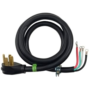
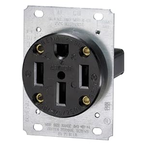
I will be installing low density 5500 W elements in both the HLT and Boil Keggle this week. Currently I have a 50 amp breaker to a 50 amp GFCI spa panel that goes to a 50 amp 14-50R outlet, like the one below.

5194KvhUSjL._SL500_AA300_.jpg


http://www.amazon.com/dp/B00009W3AA/?tag=skimlinks_replacement-20

Eventually I will go to a HERMS but I have been very happy with my cooler and would not mind continuing to use it. I do have another keg to convert to a MLT when I am ready.

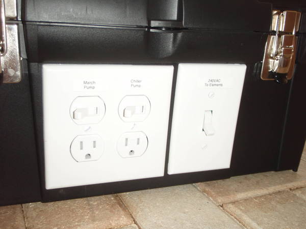
For now I would be fine with a manual setup. For instance, hitting a switch to turn the HLT element off when it hits strike or mash out temperatures. I have not been able to find much information about a setup like this, which leads me to believe that it might not be practical. The biggest issue that I can see is a high boil off rate if I don't throttle the 5500 w element in the boil keggle. Would it be possible to wire up the element directly to a 14-50 male plug then control it from the breaker? It seems like almost everyone uses a three wire connection, not a four (two hots and a ground for 220, if I'm not mistaken). I know that isn't ideal but plenty of warehouses control their lighting by switching breakers.

My biggest hesitation on using a PID or two is that I will eventually build a HERMS and I would hate to spend a couple hundred dollars on a control panel and only use it for a year or so. I tend to like very basic set ups until I feel comfortable building something advanced, not big on small steps. If I do implement automation I was thinking a basic setup like P-J suggested in post #16 in this thread.

How about this:


(Click the image for a full scale printable diagram for 11" x17" paper)

One PID (and 1 temp probe in the HLT). As Walker stated there is no need for a second temp probe. The boil is controlled using manual mode.

The contactors are $14.50 each so they certainly will not break the bank.

I've gone back and forth on this and would love to get a couple opinions. The automation would be nice but if I go that route I would really like to future proof it as much as possible. Thanks in advance.
 
Last edited by a moderator:
...
I've gone back and forth on this and would love to get a couple opinions. The automation would be nice but if I go that route I would really like to future proof it as much as possible. Thanks in advance.
There are many possibilities. If you want to go with PID control it can be done relative cheaply without throwing away lots of dollars. A setup can be placed in a $29 project box like this one from Auberins:
Pbox2a.jpg


Then - skip the relays and save even more. All of the components can be reused in any other build that you choose to take on down the road.

How about this diagram?
(Click the image for a larger pix)


Or if you come up with something different, I'll draw a diagram for you. No?

P-J
 
Not trying to thread jack, but P-J what are the benefits/advantages between your diagram added by the original poster using the contactors and the one you provided simply using a DPDT switch? It appears they will accomplish the same thing but just wired up differently.
 
Not trying to thread jack, but P-J what are the benefits/advantages between your diagram added by the original poster using the contactors and the one you provided simply using a DPDT switch? It appears they will accomplish the same thing but just wired up differently.
They both accomplish the same thing. The difference is the second one can be installed in an inexpensive box that is already setup for such a project. Dollars are not thrown away for getting started on an electric brew rig that might evolve and change down the road. Switches are a lot cheaper than contactors and they take up the same room as the switch that would control the contactor in the first place.

My object here is not the "bling" thing but to give brewers options for getting started without throwing tons of cash at it.

IMHO...
 
I do basically the same thing with my heatstick; when I reach strike temp, I unplug it. Works fine. I would think a switch with a mounted element would be even more convenient.
 
My biggest hesitation on using a PID or two is that I will eventually build a HERMS and I would hate to spend a couple hundred dollars on a control panel and only use it for a year or so.

click the link in my sig... it may not be what you're after, but it might be too. I'm building a HERMS setup around it. YMMV. :)
 
manual control is fine for when you are heating, say, your HLT to mash in temps. once you hit the temperature you want, unplug the heater. however if you need to tightly maintain a specific constant temperature, its just too much work to flip the switch on and off several times per minute for long periods of time. once you go HERMS, you pretty much need a controller.
 
If you decide to use a switch, this is available at Home Depot. I mounted one of these in a waterproof cover, also from Home Depot. I have another switching the 240VAC on my control box. You could use this switch to make a pretty simple manual control, like I did, on the wall.

Leviton_30A_240V_DPST_Switch.jpg


240V_power_switch.JPG


Toolbox_Front_Panel.JPG
 
They both accomplish the same thing. The difference is the second one can be installed in an inexpensive box that is already setup for such a project. Dollars are not thrown away for getting started on an electric brew rig that might evolve and change down the road. Switches are a lot cheaper than contactors and they take up the same room as the switch that would control the contactor in the first place.

My object here is not the "bling" thing but to give brewers options for getting started without throwing tons of cash at it.

IMHO...

This looks great, the PID, SSR, Heat Sink and RTD sensor can be got for about $100. All the switches and plugs would have been needed anyway. Not quite as bad as I was thinking.

Seems as if people are split on using a 25 amp or a 40 amp SSR and Heat sync for a 5500 w element (draw should be 23 amps). I feel like the 25 amp would be fine with the build in factor of safety but feel free to correct me if I'm wrong.

Now that I've got the automation bug I am debating going ahead and setting up a HERMS. I have a 50' 1/2" immersion cooler that I could use as the heat exchanger in the HLT then move to the boil keggle for cooling after the boil is complete. This is the copper I am planning on installing in the HLT for a more permanent solution eventually when I go the counter flow chiller or plate chiller route.

If I were to use a second PID to control the mash temp what is the best way to wire it up (assuming I do need a second PID, SSR, Heat Sink, and RTD)? Does it need to control the pump since the pump will be running continuously throughout the entire mash? Couldn't I just set the HLT at the mash temp (or a few degrees hotter), turn on the pump, then let it run until I am ready to mash out? Would I be able to just monitor the temperature with a PID without controlling the pumps? Sorry for the rapid fire questions, just trying to get some clarification.

I'm also on the fence about the whether or not the RTD should be placed on the output of the HERMS coil or the output of the MLT? Most of the information that I've found seems to favor on the output of the HERMS coil but I noticed on Kai's setup that it is on the output of the MLT. He states that when it was on the outlet of the HERMS the temperature always matched what the HLT was at, which makes sense with a big heat exchanger. I could see advantages to both ways. Maybe some trial and error is called for.

I found quite a bit of good information in this thread regarding PID controls in a HERMS set up.

I am assuming that it would be bad for the copper to touch the electric element so I would need to build something for it to sit on the lip of the keggle and hold the bottom above the element.

Anything that I am overlooking?
 
IMO manual control for the HLT will work fine, insulation will help to maintain temp once reached. The big advantage of a controller for the BK is that you can achieve very quick times to reach boiling with a lot of power and then throttle back. IMO, depending on batch size, 5500w will be too much to run at 100% in the BK. 4500w for 10 gal batches or 3000-3500 for 5 gallon batches should work fairly well depending on pot size and ambient temps.

Elements are cheap and easy to install, play around till you find the size that works well at 100% power. It can be as simple or a complicated as you wish.
 
Seems as if people are split on using a 25 amp or a 40 amp SSR and Heat sync for a 5500 w element (draw should be 23 amps). I feel like the 25 amp would be fine with the build in factor of safety but feel free to correct me if I'm wrong.

I use 25A Crydom SSRs. They are attached to a very good (conductive) heat sink. They have worked perfectly for many batches, so I can attest to their suitability in the exact system you're considering.

However, I'd use 40A if I could get them cheap enough. Why not?
 
Not trying to thread jack, but P-J what are the benefits/advantages between your diagram added by the original poster using the contactors and the one you provided simply using a DPDT switch? It appears they will accomplish the same thing but just wired up differently.

The nice thing about the contactors though is the safety feature of them (I went the contactor route on my build). As Walker advised me, when you use the contactors you wire the contactors via a 120v line through your switches. So intead of having a switch on 240v, it is only 120v. So you never are touching anything (with potentially wet hands) that is 240v. I like the idea of that.

Also, I believe that if they fail, they fail open. i.e. no current passing to the element
 
If you decide to use a switch, this is available at Home Depot. I mounted one of these in a waterproof cover, also from Home Depot. I have another switching the 240VAC on my control box. You could use this switch to make a pretty simple manual control, like I did, on the wall.

Toolbox_Front_Panel.JPG

Passedpawn, I really like that setup. Nice and simple.

IMO manual control for the HLT will work fine, insulation will help to maintain temp once reached. The big advantage of a controller for the BK is that you can achieve very quick times to reach boiling with a lot of power and then throttle back. IMO, depending on batch size, 5500w will be too much to run at 100% in the BK. 4500w for 10 gal batches or 3000-3500 for 5 gallon batches should work fairly well depending on pot size and ambient temps.

Elements are cheap and easy to install, play around till you find the size that works well at 100% power. It can be as simple or a complicated as you wish.

Wilserbrewer - I typically do 5 gallon batches (start boil at 7.5 gal and finish with 6). If I go manual I will probably scale back to 3500w. Speed isn't a huge issue but anything to shorten a brew day is helpful. Ambient temps aren't too much of a problem in Houston, it ranges from "hot" to "f-ing hot".
 
Tony,

Good post.! I'll try to answer your questions after each:

This looks great, the PID, SSR, Heat Sink and RTD sensor can be got for about $100. All the switches and plugs would have been needed anyway. Not quite as bad as I was thinking.

Seems as if people are split on using a 25 amp or a 40 amp SSR and Heat sync for a 5500 w element (draw should be 23 amps). I feel like the 25 amp would be fine with the build in factor of safety but feel free to correct me if I'm wrong.
I would definitely use a 40A SSR. You are really pushing the limit margin on a 25A SSR. The more current they carry the more heat is generated within the unit. It is not a switch - it's an electronic module. I think it is well worth the few dollars to get the higher capacity unit.

Now that I've got the automation bug I am debating going ahead and setting up a HERMS. I have a 50' 1/2" immersion cooler that I could use as the heat exchanger in the HLT then move to the boil keggle for cooling after the boil is complete. This is the copper I am planning on installing in the HLT for a more permanent solution eventually when I go the counter flow chiller or plate chiller route.
I believe the HERMS coil is a valuable addition to you setup - IF - you are plan on using a keg for your MASH tun. (If you are going to use an insulated cooler, it's not needed.) With a good HERMS setup, you will only lose a degree or two during recirculation. (Just set the temp up for the loss difference) It is also important that the HLT water is kept moving over the HERMS coil. Use a second pump or a stirrer to do this) BTW you only need 25' of 1/2" OD copper for this HERMS coil. It's more than enough. You certainly can use the full length as you said and then use it for cooling in the BOIL kettle. Good idea and this could be your permanent solution as you already have it.. Why mess with something that is successful as is?

If I were to use a second PID to control the mash temp what is the best way to wire it up (assuming I do need a second PID, SSR, Heat Sink, and RTD)? Does it need to control the pump since the pump will be running continuously throughout the entire mash? Couldn't I just set the HLT at the mash temp (or a few degrees hotter), turn on the pump, then let it run until I am ready to mash out? Would I be able to just monitor the temperature with a PID without controlling the pumps? Sorry for the rapid fire questions, just trying to get some clarification.
IMHO - there is no need for a second PID - unless - you plan on doing back to back batches. (MASH-In the second batch while running the Boil on the first. If you decide to go this route, I'd be glad to come up with a new diagram for you) The pump should run the Mash water through the HERMS continuously. The pump would be on for the full mash time. Temp is controlled with the PID controlling the HLT temp. BTW, There is absolutely no need for you to do a mash out with batch sparging. The current (modern) grain bill that you would be using would not require this step.

I'm also on the fence about the whether or not the RTD should be placed on the output of the HERMS coil or the output of the MLT? Most of the information that I've found seems to favor on the output of the HERMS coil but I noticed on Kai's setup that it is on the output of the MLT. He states that when it was on the outlet of the HERMS the temperature always matched what the HLT was at, which makes sense with a big heat exchanger. I could see advantages to both ways. Maybe some trial and error is called for.
I would place (My strong opinion on this one) the RTD probe to monitor and control the HLT temperature. I would not place it anywhere else. Keep in mind that this temp sensor is controlling the HLT temp.

I found quite a bit of good information in this thread regarding PID controls in a HERMS set up.
Have not looked yet but will.

I am assuming that it would be bad for the copper to touch the electric element so I would need to build something for it to sit on the lip of the keggle and hold the bottom above the element.
Correct. Just fabricate a heavy copper wire loop to hold the coil a few inches above the element. You can wrap the support over the edge of the kettle.
Actually, I really don't think it would be an issue. Once you build your E-system you will be doing a 'wet' test run. Try it then and then decide. No?

Anything that I am overlooking?

Great post.!!! Hope I didn't miss anything.

I'll ask for a favor from you. (IF you can feel comfortable doing it - IF not Don't.!) PM me your # and a good time to call. I'd love to talk out some of the detail a little more.

Best regards.
Paul
P-J
 
I suspended my herms coil over the element by using the copper ground for 8/3 romex. I made a square U shape that sits on the keggle bottom and wrapped the other ends around the bottom most pipe of the coil, works good
 
I suspended my herms coil over the element by using the copper ground for 8/3 romex. I made a square U shape that sits on the keggle bottom and wrapped the other ends around the bottom most pipe of the coil, works good

Do you have a picture of this? I don't quite get it.
 
I suspended my herms coil over the element by using the copper ground for 8/3 romex. I made a square U shape that sits on the keggle bottom and wrapped the other ends around the bottom most pipe of the coil, works good

If your herms coil is removable, why not just fashion the coil itself so that it rests over the element. If it's copper tubing, you should be able to do that.
 
Mine is not removable, so I had to fashion something to hold it up. If there is not a pic in my build in my signature, I think I have one on my build thread on theelectricbrewery. It is reverse polarity brewery build. At work, can't look at it now, I can get a detailed pic later.
 
I would definitely use a 40A SSR. You are really pushing the limit margin on a 25A SSR. The more current they carry the more heat is generated within the unit. It is not a switch - it's an electronic module. I think it is well worth the few dollars to get the higher capacity unit.

Fair enough. At Auber the cost for a 25 amp SSR and heat sink is about $25 while the 40 amp is about $40. $15 won't break the bank. I am planning on the Auber SYL-2352 PID for $45. My biggest question now is if I would like to install a safe start interlock to avoid me accidentally dry firing the elements/pumps. If it can be done for around $50 I think it would be worth it. If not, at $20 per element it might not.

I believe the HERMS coil is a valuable addition to you setup - IF - you are plan on using a keg for your MASH tun. (If you are going to use an insulated cooler, it's not needed.) With a good HERMS setup, you will only lose a degree or two during recirculation. (Just set the temp up for the loss difference) It is also important that the HLT water is kept moving over the HERMS coil. Use a second pump or a stirrer to do this) BTW you only need 25' of 1/2" OD copper for this HERMS coil. It's more than enough. You certainly can use the full length as you said and then use it for cooling in the BOIL kettle. Good idea and this could be your permanent solution as you already have it.. Why mess with something that is successful as is?

I will keep using for cooler for a little while but it is good to know that I won't need any additional equipment aside from the keg fittings/false bottom once I go that route. As I mentioned before I have a keg with the top cut off already. I've seen that the clarity of the beer can be improved with the constant recirculating, would there be any downside to recirculating through the HERMS coil while using the cooler?

IMHO - there is no need for a second PID - unless - you plan on doing back to back batches. (MASH-In the second batch while running the Boil on the first. If you decide to go this route, I'd be glad to come up with a new diagram for you) The pump should run the Mash water through the HERMS continuously. The pump would be on for the full mash time. Temp is controlled with the PID controlling the HLT temp. BTW, There is absolutely no need for you to do a mash out with batch sparging. The current (modern) grain bill that you would be using would not require this step.

Currently I often do back to back batches, I like brewing more than drinking and like to keep a variety on tap (although I like drinking quite a bit). I was ready to move forward without it until I got a 50 amp GFCI setup instead of the 30 amp that most people seem to use. Now I am debating trying to tweak the system to be able to do back to backs, which I'm guessing would mean downgrading the 5500 watt elements to 4500 watt. I would absolutely love to have the option for back to backs, but when the boil is finished I still have about 45 minutes of wort chilling/whirlpooling/waiting for whirlpool to settle/draining to carboy before I would be able to start filling the boil kettle. That get me at least half way through my second mash. The time savings just don't seem to be there when mashing in a keg since the 20-30 minutes of preheating the cooler would not be included. That being said, lets see if it is possible.

5500 W = 22.91 A at 240 V
4500 W = 18.75 A
Pumps = 1.4 A

So if both elements and pumps were running, not including the control panel, I would be looking at:

49 amps with the 5500 watt element
40.5 amps with the 4500 watt element

I know the 80% continuous load rule, which the 5500 clearly breaks, and the 4500 would with another couple of amps going to the control panel. Looks like back to back isn't in the cards for me. It is not worth it for me to go down to 3500 watt elements, I need the speed baby.

I would place (My strong opinion on this one) the RTD probe to monitor and control the HLT temperature. I would not place it anywhere else. Keep in mind that this temp sensor is controlling the HLT temp.

My thought was to place two sensors, one exiting the HERMS coil and one permanently mounted in the HLT. I agree that the control of the HLT temp should be controlled with a RTD mounted into the keg, but I was thinking having one at the exit of the HERMS coil would be a way to check that the liquid exiting was being heated properly. This may be unnecessary, but I have no experience with using a HERMS setup and would like some verification that it is working. May or may not do this just for my piece of mind.

Correct. Just fabricate a heavy copper wire loop to hold the coil a few inches above the element. You can wrap the support over the edge of the kettle.
Actually, I really don't think it would be an issue. Once you build your E-system you will be doing a 'wet' test run. Try it then and then decide. No?

I've got some ideas, once the element is mounted I will figure it out. Should be simple enough once I see it all put together. If I need to re-bend or re-solder the coil in order to maximize the surface area in contact with the least amount of water it's not a problem.

Thanks so much for the help.
 
5500 W = 22.91 A at 240 V
4500 W = 18.75 A
Pumps = 1.4 A

So if both elements and pumps were running, not including the control panel, I would be looking at:

49 amps with the 5500 watt element
40.5 amps with the 4500 watt element

I know the 80% continuous load rule, which the 5500 clearly breaks, and the 4500 would with another couple of amps going to the control panel. Looks like back to back isn't in the cards for me. It is not worth it for me to go down to 3500 watt elements, I need the speed baby.
Keep in mind: The "80% rule" does NOT apply to a single outlet circuit.
Also, the "rule" applies to the home designer and/or the electrician installing the electrical circuits. It does not apply to the home owner.

A 4500W element in your HLT and a 5500W element in the BOIL would solve your power concerns for back to back brews.
 
I am in the middle of designing and building and electric brewery and was wondering if it would be possible to controlled the heating elements manually at either the breaker or my installing an inline switch.
Do not use a circuit breaker in your panel as a switch. That's not the purpose of a breaker.

Same thing with plugging/unplugging high current heating elements from the wall to turn them on/off. That's not safe. A switch of some sort that is meant to be switched should be used. A wall outlet/socket combination is not a switch.

In the end, anyone can do anything they like of course. Just pointing out what's safe/normal.

Kal

Hi Kal - I agree with you, just being devil's advocate here. If you used the breaker as a switch, is it truly unsafe? I mean as long as the box is closed up, I can't see how this would be unsafe. especially since the user would likely only be brewing once a week at most.

Not saying this is correct usage for a circuit breaker, but not sure it would technically be unsafe to do.


TonySwank - why not use a contactor with a switch to control your heating elements? Pretty cheap addition. That is how I put mine together. The PID can't activate the element unless I manually give the element power through my switch to the contactor.
 
Hi Kal - I agree with you, just being devil's advocate here. If you used the breaker as a switch, is it truly unsafe? I mean as long as the box is closed up, I can't see how this would be unsafe. especially since the user would likely only be brewing once a week at most.

Not saying this is correct usage for a circuit breaker, but not sure it would technically be unsafe to do.
Sorry, unsafe is probably the wrong choice of words in the case of using a breaker as a switch.

Kal
 
Keep in mind: The "80% rule" does NOT apply to a single outlet circuit.
Also, the "rule" applies to the home designer and/or the electrician installing the electrical circuits. It does not apply to the home owner.

A 4500W element in your HLT and a 5500W element in the BOIL would solve your power concerns for back to back brews.

Thanks for the clarification about the 80% rule, I misunderstood it before. Now to decide if back to back batches is worth another $150 or so in PID/SSR/Heat Sink/misc. This scope/budget creep came up quickly.

Do not use a circuit breaker in your panel as a switch. That's not the purpose of a breaker.

Same thing with plugging/unplugging high current heating elements from the wall to turn them on/off. That's not safe. A switch of some sort that is meant to be switched should be used. A wall outlet/socket combination is not a switch.

Kai, I completely agree and I am definitely beyond using the breaker as a switch, it is a less than ideal situation at best. The question was more out of curiosity, but since we're dealing with electricity there should be no confusion out there.

TonySwank - why not use a contactor with a switch to control your heating elements? Pretty cheap addition. That is how I put mine together. The PID can't activate the element unless I manually give the element power through my switch to the contactor.

Just a quick clarification about contactors, once power is cut to an element the contactor will open and a the connected switch will need to be activated to power the element again. I'm assuming the purpose of these are typically to ensure the element is not hot when power to the control panel is activated. What type of switches/buttons are commonly used with contactors? Is the general consensus that contactors are a better solution than using a double pole double throw switch between the elements?
 
Well it certainly isn't a "normal" use for a circuit breaker. Ok no more semantics crap from me - the lowly electrical newb. Best,
 
Just a quick clarification about contactors, once power is cut to an element the contactor will open and a the connected switch will need to be activated to power the element again.
?

Correct - No power to contactor (switch off position) = contactor open and no power to element.

I'm assuming the purpose of these are typically to ensure the element is not hot when power to the control panel is activated.

That was my purpose and I have two outlets on my box, so I went with an On-Off-On Switch to toggle between each outlet and off (one contactor for each outlet). Purpose being:

1. Two elements can't be on at the same time;
2. in the off position, there is no way for the PID to turn the elements on (your point above).

What type of switches/buttons are commonly used with contactors?

I used a basic 10amp on-off-on (SPDT) switch from Home depot
EDIT - I put the switch on a line that had a 1amp FB fuse, so you could in theory never get more that 1amp from the line to the switch.


Is the general consensus that contactors are a better solution than using a double pole double throw switch between the elements?

I think this is a builder's preference - but I like the idea of never touching something that has 240v running through it (with potentially wet hands). The contactors are powered by 120v.
 
I think this is a builder's preference - but I like the idea of never touching something that has 240v running through it (with potentially wet hands). The contactors are powered by 120v.
Agreed.

Generally speaking, if you look at how control panels and such are designed, you never put high current/voltage items on the door or front of the panel. You put lower power "control" stuff on the panel and the heavy stuff is permanently bolted to the backplane of the panel. One big reason for doing this is that the high current wires used by the big power stuff is stiff. You want to have it installed such that it doesn't move. So all wire that gets bent/pulled/pushed as the swinging door gets opened/closed is lower amperage wiring. This is done for safety and ease of installation/use.

Kal
 
Alright, thanks so much for the help everyone. I am planning on going the route similar to what I initially posted, using the contactors and only having one element active at a time. I will most likely use a 4500 watt element in the HLT so when I feel like adding another PID/SSR/Heat Sink I will be able to run both elements at the same time for back to back batches.

Auberin-wiring1-a4-4500w-30a.jpg


My biggest question now is getting power to the control panel. I have a 50 amp plug (14-50R) and will be using a 4 wire range power cord like this one.

419RxL1ix5L._SL500_AA300_.jpg


The issue I am having is finding 50 amp plugs and receptacles, the few that I have found don't look like they would work well. Right now it looks like my options are to either hardwire the power cord to the control panel, which is what I am leaning towards, or downgrade to using 30 amp plugs. The 30 amp plugs should not be an issue but it would be nice to have the full 50 amps available in the future. I saw that Walker hardwired his and as long as the cord is attached to the external box well the internal components shouldn't be stressed.

I will be using a DIN Power Rail for power distribution. Never used one before but looks like it should be a nice space saver. Any tricks?

For the pumps I will be using a duplex outlet with each outlet wired to the an individual switch, similar to what PJ mentioned here. Never wired up a duplex outlet individually but don't see any issues.

Welcome.

You might consider using a duplex outlet. It might make your life a little easier.

duplex-outlet.jpg


The arrows point to a small break away tab. Just snap off the one on the left side (brass terminal screws). This way you will eliminate some wiring complexity as the neutral and ground will be common for both outlets.

You would only need to cut one hole in the box as well.

Can't think of anything else right now. Any comments are welcome. You guys have been a huge help and I am really excited to get the project going.
 
Last edited by a moderator:
Agreed.

Generally speaking, if you look at how control panels and such are designed, you never put high current/voltage items on the door or front of the panel. You put lower power "control" stuff on the panel and the heavy stuff is permanently bolted to the backplane of the panel. One big reason for doing this is that the high current wires used by the big power stuff is stiff. You want to have it installed such that it doesn't move. So all wire that gets bent/pulled/pushed as the swinging door gets opened/closed is lower amperage wiring. This is done for safety and ease of installation/use.

Kal

I never thought of this... I will work this into my future build. Thanks for helping to keep my hairs straight.
 
Upon thinking more about this set up, I have a question...

Is the contactor simply insurance to prevent the PID from dry heating the element? If so, wouldn't a $1 switch for the PID power be a cheaper solution than the contactor? Am I missing a benefit of the contactor?

I am assuming that if the PID is powered off the SSR is open (off)... Is that a correct assumption?
 
Back
Top