You are using an out of date browser. It may not display this or other websites correctly.
You should upgrade or use an alternative browser.
You should upgrade or use an alternative browser.
List of PJ Electrical Diagrams
- Thread starter OatStraw
- Start date

Help Support Homebrew Talk:
This site may earn a commission from merchant affiliate
links, including eBay, Amazon, and others.
Wolfairious
Well-Known Member
- Joined
- Jan 11, 2015
- Messages
- 101
- Reaction score
- 22
Anyone has the 50a switched and interlocked one without a relay?
Anyone has the 50a switched and interlocked one without a relay?
What have you got against relays? I'm not familiar with any high current interlock designs that don't use relays.
Brew on

Wolfairious
Well-Known Member
- Joined
- Jan 11, 2015
- Messages
- 101
- Reaction score
- 22
This was the one I was talking about. excuse the quality. I had to scan a print-out and then color in the lines with pic editor.

shadowrayz
Active Member
I have been brewing for a couple of years (all grain using propane) and finally starting to gather parts for my electric controller. I went to see if P-J was still posting wiring diagrams and it looks as though I was a bit too late. Started reading the thread and saw that he was not in good health and sure hope he is still around.
Does anyone have a wiring diagram for the following:
I am running a 3-wire/30A (A, B, and Ground) 10 gauge extension cord from a dryer outlet in my basement for the 220v side.
I will also be running a seperate 110v line into the controller to run pumps as well as the Contactor coils.
I will be running two 5500w elements (one at a time using a three-way selector switch).
2 REX-C100-FK02-V*AN PID's
2 Fotek SSR 40A SSR's
3 250v/30a - 110v coil Contactors
I have drawn up a rough wiring diagram. Is there someone that can check my work to see if this can work or not? Add / Change / Subtract?
Thank you in advance!
What are you planning for GFCI protection? Brewing without GFCI represents an electrocution hazard to you.
I recommend you double check the wiring of your dryer outlet to be sure it is really hot-hot-gnd, and not hot-hot-neutral. My understanding is that most are H-H-N.
Note that the FK02 version uses type K thermocouples for temp input, so PT100 RTD's cannot be used. Any probe extension wire needs to be type K compatible thermocouple extension wire. Ordinary copper wire will give you temperature errors.
The SSR output of the C100 is on terminals 4 (+) & 5 (-), not 3 & 4 as you show. http://www.rkcinst.co.jp/english/pdf_manual/imnzc22e1.pdf
Brew on

$10.99 ($31.16 / Ounce)
Hornindal Kveik Yeast for Homebrewing - Mead, Cider, Wine, Beer - 10g Packet - Saccharomyces Cerevisiae - Sold by Shadowhive.com
Shadowhive


$22.00 ($623.23 / Ounce)
AMZLMPKNTW Ball Lock Sample Faucet 30cm Reinforced Silicone Hose Secondary Fermentation Homebrew Kegging joyful
无为中南商贸有限公司


$58.16
HUIZHUGS Brewing Equipment Keg Ball Lock Faucet 30cm Reinforced Silicone Hose Secondary Fermentation Homebrew Kegging Brewing Equipment
xiangshuizhenzhanglingfengshop

$53.24
1pc Hose Barb/MFL 1.5" Tri Clamp to Ball Lock Post Liquid Gas Homebrew Kegging Fermentation Parts Brewer Hardware SUS304(Liquid Hose Barb)
yunchengshiyanhuqucuichendianzishangwuyouxiangongsi

$479.00
$559.00
EdgeStar KC1000SS Craft Brew Kegerator for 1/6 Barrel and Cornelius Kegs
Amazon.com


$7.79 ($7.79 / Count)
Craft A Brew - LalBrew Voss™ - Kveik Ale Yeast - For Craft Lagers - Ingredients for Home Brewing - Beer Making Supplies - (1 Pack)
Craft a Brew


$53.24
1pc Hose Barb/MFL 1.5" Tri Clamp to Ball Lock Post Liquid Gas Homebrew Kegging Fermentation Parts Brewer Hardware SUS304(Liquid Hose Barb)
Guangshui Weilu You Trading Co., Ltd


$176.97
1pc Commercial Keg Manifold 2" Tri Clamp,Ball Lock Tapping Head,Pressure Gauge/Adjustable PRV for Kegging,Fermentation Control
hanhanbaihuoxiaoshoudian


$33.99 ($17.00 / Count)
$41.99 ($21.00 / Count)
2 Pack 1 Gallon Large Fermentation Jars with 3 Airlocks and 2 SCREW Lids(100% Airtight Heavy Duty Lid w Silicone) - Wide Mouth Glass Jars w Scale Mark - Pickle Jars for Sauerkraut, Sourdough Starter
Qianfenie Direct
![Craft A Brew - Safale BE-256 Yeast - Fermentis - Belgian Ale Dry Yeast - For Belgian & Strong Ales - Ingredients for Home Brewing - Beer Making Supplies - [3 Pack]](https://m.media-amazon.com/images/I/51bcKEwQmWL._SL500_.jpg)


$20.94
$29.99
The Brew Your Own Big Book of Clone Recipes: Featuring 300 Homebrew Recipes from Your Favorite Breweries
Amazon.com


$719.00
$799.00
EdgeStar KC2000TWIN Full Size Dual Tap Kegerator & Draft Beer Dispenser - Black
Amazon.com


I have been brewing for a couple of years (all grain using propane) and finally starting to gather parts for my electric controller. I went to see if P-J was still posting wiring diagrams and it looks as though I was a bit too late. Started reading the thread and saw that he was not in good health and sure hope he is still around.
Does anyone have a wiring diagram for the following:
I am running a 3-wire/30A (A, B, and Ground) 10 gauge extension cord from a dryer outlet in my basement for the 220v side.
I will also be running a seperate 110v line into the controller to run pumps as well as the Contactor coils.
I will be running two 5500w elements (one at a time using a three-way selector switch).
2 REX-C100-FK02-V*AN PID's
2 Fotek SSR 40A SSR's
3 250v/30a - 110v coil Contactors
I have drawn up a rough wiring diagram. Is there someone that can check my work to see if this can work or not? Add / Change / Subtract?
Thank you in advance!
Is one of the elements going to be in you boil kettle? If so, the REX C100 does not have a manual output level control function, so is not suitable for controlling boil vigor.
Brew on
Marquez
Well-Known Member
Search for images using
as search terms and you'll find MANY of his diagrams.
"homebrewtalk p-j diagrams"as search terms and you'll find MANY of his diagrams.
shadowrayz
Active Member
What are you planning for GFCI protection? Brewing without GFCI represents an electrocution hazard to you.
I recommend you double check the wiring of your dryer outlet to be sure it is really hot-hot-gnd, and not hot-hot-neutral. My understanding is that most are H-H-N.
Note that the FK02 version uses type K thermocouples for temp input, so PT100 RTD's cannot be used. Any probe extension wire needs to be type K compatible thermocouple extension wire. Ordinary copper wire will give you temperature errors.
The SSR output of the C100 is on terminals 4 (+) & 5 (-), not 3 & 4 as you show. http://www.rkcinst.co.jp/english/pdf_manual/imnzc22e1.pdf
Brew on
For the Dryer outlet, Since this is not a four-wire, you cannot make a neutral. You have to use it as a ground. Even in my Main Panel, the ground wire is on the ground bar along with all neutrals wired in my house.
<I just watch a video of an electrician installing a GFCI using 3-wire.>
Looks like I will be installing one (I am glad because I don't feel like dying, lol).
For the 110v side, I was told to run a regular 110v into the control panel and use it for my pumps, PID, and coils.
Thanks!:rockin:

shadowrayz
Active Member
Is one of the elements going to be in you boil kettle? If so, the REX C100 does not have a manual output level control function, so is not suitable for controlling boil vigor.
Brew on
Could a 220v voltage regulator work in this instance between the contactor and the output to the elements?
Thanks!
Could a 220v voltage regulator work in this instance between the contactor and the output to the elements?
Thanks!
Best solution is an SSVR. Kind of like an SSR, but controlled by a potentiometer (variable resistor) to give PWM output. Just be sure you use a high quality potentiometer with the SSVR, as line voltage is connected to the potentiometer (from the SSVR control terminals.)
Brew on
For the Dryer outlet, Since this is not a four-wire, you cannot make a neutral. You have to use it as a ground. Even in my Main Panel, the ground wire is on the ground bar along with all neutrals wired in my house.
<I just watch a video of an electrician installing a GFCI using 3-wire.>
Looks like I will be installing one (I am glad because I don't feel like dying, lol).
For the 110v side, I was told to run a regular 110v into the control panel and use it for my pumps, PID, and coils.
Thanks!:rockin:
It's possible to derive a four wire circuit from a three wire with the H-H-N configuration. If you do this, you don't need a separate outlet to get 120V in your panel. The caveat is that the derived ground might not actually be at earth potential if there are significant currents on the neutral wire (due to 120V loads.) Shouldn't be an issue unless you actually earth ground something connected to the derived ground. The following diagram shows how to connect the GFCI breaker in a spa panel to derive a four wire feed from a three wire, H-H-N feed (yellow is neutral in the diagram.)

Brew on
shadowrayz
Active Member
It's possible to derive a four wire circuit from a three wire with the H-H-N configuration. If you do this, you don't need a separate outlet to get 120V in your panel. The caveat is that the derived ground might not actually be at earth potential if there are significant currents on the neutral wire (due to 120V loads.) Shouldn't be an issue unless you actually earth ground something connected to the derived ground. The following diagram shows how to connect the GFCI breaker in a spa panel to derive a four wire feed from a three wire, H-H-N feed (yellow is neutral in the diagram.)
View attachment 381894
Brew on
So, this is NOT SAFE as there is no true ground, correct? Wonder what a professional electrician thinks of this. If it is safe, I would like to speak with someone who is using this exact setup.
I may be moving soon and hoping that there will be a 4-wire 220v to use so I do not have to MacGyver the 3-wire and have a potential to getting killed. I may have to stick with propane until then.
I am not a certified electrician, but I consider the arrangement safe (and I'm pretty anal about safety.) I believe P-J first posted this method of deriving a four wire feed from a three wire feed (second post in this thread. Unfortunately the pic
If you read the thread linked above, you will see all the debate about whether or not this arrangement is safe. I'll throw in some calculations to illustrate what a realistic scenario looks like. With two pumps running at once, plus the miscellaneous low wattage electronics, the total 120V current would be about 5A. Thus the current flowing thru the neutral wire would be 5A. 10AWG wire has a resistance of 1 ohm/1000 ft. If you have a 100 ft run of 10AWG in your installation, the resistance is 0.1 ohm. The max voltage (relative to ground) at the load end of the neutral is 5A * 0.1 ohm = 0.5V. A resistance of up to 2 ohms in the ground path is generally considered acceptable, and the derived ground would be at 5% of that.
Brew on
shadowrayz
Active Member
I am not a certified electrician, but I consider the arrangement safe (and I'm pretty anal about safety.) I believe P-J first posted this method of deriving a four wire feed from a three wire feed (second post in this thread. Unfortunately the picin the post has disappeared, but was the same as I posted above.) The GFCI still performs its function to prevent you from getting more than ~5mA of current from a shock. Even if the "ground" isn't at 0 V, it will still shunt and sink any current available from a short to a source at a high enough voltage to be a safety concern. I don't use this arrangement myself, but I know there are several users on HBT.
If you read the thread linked above, you will see all the debate about whether or not this arrangement is safe. I'll throw in some calculations to illustrate what a realistic scenario looks like. With two pumps running at once, plus the miscellaneous low wattage electronics, the total 120V current would be about 5A. Thus the current flowing thru the neutral wire would be 5A. 10AWG wire has a resistance of 1 ohm/1000 ft. If you have a 100 ft run of 10AWG in your installation, the resistance is 0.1 ohm. The max voltage (relative to ground) at the load end of the neutral is 5A * 0.1 ohm = 0.5V. A resistance of up to 2 ohms in the ground path is generally considered acceptable, and the derived ground would be at 5% of that.
Brew on
Thank you! Great information.
If anyone reading this has a similar setup, I would like to discuss.
Much appreciated!
shadowrayz
Active Member
Note that the FK02 version uses type K thermocouples for temp input, so PT100 RTD's cannot be used. Any probe extension wire needs to be type K compatible thermocouple extension wire. Ordinary copper wire will give you temperature errors.
Hi Doug293cz ~ Will the PT100 RTD's be compatible with the Auberin SYL-2352 PID's? Since I will need to replace the REX-C100's I will need to know if I will need to replace the sensors. Thanks!
Yes, PT100 RTD's will work with the Auber SYL-2352.Hi Doug293cz ~ Will the PT100 RTD's be compatible with the Auberin SYL-2352 PID's? Since I will need to replace the REX-C100's I will need to know if I will need to replace the sensors. Thanks!
If you are going to get new controllers, I strongly recommend you consider the Auber EZBoil DSPR120 or DSPR300 (the 300 has alarm functions that the 120 does not.) They are also compatible with PT100 RTD's. The DSPR's perform the same function as a PID, and they also provide twist knob boil power control. The DSPR's temp control function works better than PID's for a mashing application. They are more stable, and much less difficult to tune (if they even need tuning.)
Brew on
shadowrayz
Active Member
Yes, PT100 RTD's will work with the Auber SYL-2352.
If you are going to get new controllers, I strongly recommend you consider the Auber EZBoil DSPR120 or DSPR300 (the 300 has alarm functions that the 120 does not.) They are also compatible with PT100 RTD's. The DSPR's perform the same function as a PID, and they also provide twist knob boil power control. The DSPR's temp control function works better than PID's for a mashing application. They are more stable, and much less difficult to tune (if they even need tuning.)
Brew on
Much appreciated! I will look into that version.
Before you buy any PID, you should look at the Auber Instruments EZBoil controllers (DSPR120 and DSPR300.) They perform the same function as a PID with manual control option, but they are easier to use and more stable than PID's. Pretty much everyone on HBT that has experience with both agrees that the EZBoil is a better choice than a PID. The EZBoil is a bit costlier than a low end PID, but if you look at the entire budget for an electrified system, the extra cost is a very small fraction of the total.Tried to open some of the wiring diagrams but couldn't get them to open. Going to build a BIAB setup with an Inkbird pid and a single pump with a 5500w single element. Any help is appreciated.
TIA
Since the P-J diagrams are getting harder and harder to find, I offer you this for consideration. You can leave out one of the pump switches and outlets, since you will only have one pump. If you want different functionality, that can be accommodated. This design has interlocks that prevent you from turning on the system if the pump or element is turned on (no surprises when you flip the main power switch.) Simpler (and cheaper) designs are possible, but they have more operator error failure modes available.

Of course the DSPR could be replaced by a PID if that's what you really want to do (terminal assignments will be different.) Other components can be substituted with equivalents as long as the voltage and current ratings are no lower than the listed components.
Brew on
Before you buy any PID, you should look at the Auber Instruments EZBoil controllers (DSPR120 and DSPR300.) They perform the same function as a PID with manual control option, but they are easier to use and more stable than PID's. Pretty much everyone on HBT that has experience with both agrees that the EZBoil is a better choice than a PID. The EZBoil is a bit costlier than a low end PID, but if you look at the entire budget for an electrified system, the extra cost is a very small fraction of the total.
Since the P-J diagrams are getting harder and harder to find, I offer you this for consideration. You can leave out one of the pump switches and outlets, since you will only have one pump. If you want different functionality, that can be accommodated. This design has interlocks that prevent you from turning on the system if the pump or element is turned on (no surprises when you flip the main power switch.) Simpler (and cheaper) designs are possible, but they have more operator error failure modes available.
View attachment 382855
Of course the DSPR could be replaced by a PID if that's what you really want to do (terminal assignments will be different.) Other components can be substituted with equivalents as long as the voltage and current ratings are no lower than the listed components.
Brew on
Doug thanks for posting this wiring diagram, this is just what I have been looking for. Im going make a order to Auber and was wondering if you would recommend parts # for the main power witch and alarm. thanks for all the help to the community.
The Auber key switch (Main Power Switch) is the SW8 (http://www.auberins.com/index.php?main_page=product_info&cPath=7_32&products_id=277.) Doesn't matter if you order the 1NO/1NC or 2NO option, as we only use 1NO block in this design.Doug thanks for posting this wiring diagram, this is just what I have been looking for. Im going make a order to Auber and was wondering if you would recommend parts # for the main power witch and alarm. thanks for all the help to the community.
The alarm is the FLBuz (110V option, http://www.auberins.com/index.php?main_page=product_info&cPath=7_33&products_id=215) or the FLBuz-120-16 (http://www.auberins.com/index.php?main_page=product_info&cPath=7_33&products_id=221.)
The design calls out either SW1 (push button) or SW16 (rotary) lighted switches for the Element Enable and Pump switches. SW1 is incorrect (as they are 2 NO blocks) and the design requires SW11 (which are 1NO/1NC, http://www.auberins.com/index.php?main_page=product_info&cPath=7_32&products_id=303.) If you use SW16's, you need to specify the 1NO/1NC option (http://www.auberins.com/index.php?main_page=product_info&cPath=7_32&products_id=349.)
Brew on
The Auber key switch (Main Power Switch) is the SW8 (http://www.auberins.com/index.php?main_page=product_info&cPath=7_32&products_id=277.) Doesn't matter if you order the 1NO/1NC or 2NO option, as we only use 1NO block in this design.
The alarm is the FLBuz (110V option, http://www.auberins.com/index.php?main_page=product_info&cPath=7_33&products_id=215) or the FLBuz-120-16 (http://www.auberins.com/index.php?main_page=product_info&cPath=7_33&products_id=221.)
The design calls out either SW1 (push button) or SW16 (rotary) lighted switches for the Element Enable and Pump switches. SW1 is incorrect (as they are 2 NO blocks) and the design requires SW11 (which are 1NO/1NC, http://www.auberins.com/index.php?main_page=product_info&cPath=7_32&products_id=303.) If you use SW16's, you need to specify the 1NO/1NC option (http://www.auberins.com/index.php?main_page=product_info&cPath=7_32&products_id=349.)
Brew on
thanks for the info and the clarification on the witches
BowAholic
Well-Known Member
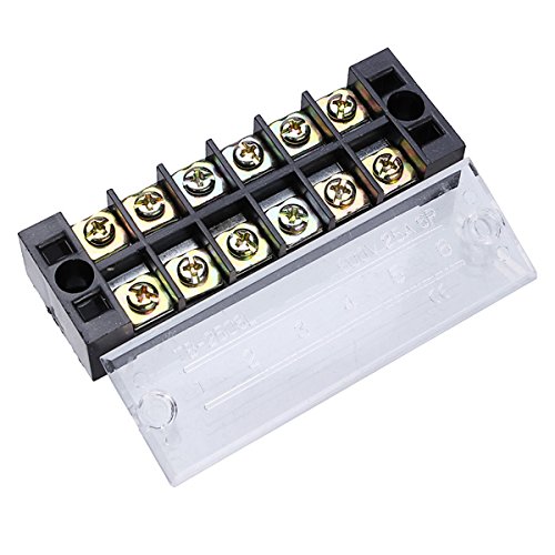
so... what is the best way to attach the smaller diameter wires to the large wires for things like the fuses and the indicator light?
thanks!

thanks!
highland_brewer
Short Circuited Brewers
so... what is the best way to attach the smaller diameter wires to the large wires for things like the fuses and the indicator light?
thanks!
IMO... a distribution block.
so... what is the best way to attach the smaller diameter wires to the large wires for things like the fuses and the indicator light?
thanks!
Terminal (or bus) strips/blocks are a good option, as pointed out by @highland_brewer. On images.google.com, search for "terminal block and jumper". You should be able to figure out how these work by looking at some of the images. Need to make sure that you buy strips/blocks rated for 240V/30A (or higher.)
You can also arrange your wire routing to put two spade or eyelet crimped wire terminations on a single device terminal like is shown in the design in this post. If you don't fully understand the design's connectivity, and how to move wires without changing the connectivity, then terminal strips are a better choice.
Brew on
BowAholic
Well-Known Member
thanks!
Another good source for terminal blocks. Especially if you use DIN mounts.
http://www.mouser.com/Search/Refine.aspx?Keyword=altec+terminal+block
http://www.mouser.com/Search/Refine.aspx?Keyword=altec+terminal+block
BowAholic
Well-Known Member
thanks everyone... now, the next question...using the diagram I posted above... will this SSR be wired just like it looks in the diagram? It doesn't have the "1-2-3-4" but instead has "L1-L2-T1-T2"...

PapaFoxtrot
Well-Known Member
That one has two separate channels.
Similar threads
- Replies
- 14
- Views
- 3K
- Replies
- 6
- Views
- 2K
- Replies
- 1
- Views
- 2K
- Replies
- 1
- Views
- 1K
