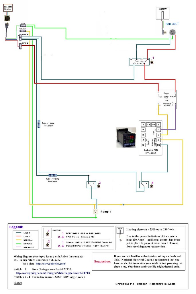
I guess what I need to do is figure out how to scan my wiring diagram (actually taken and modified from one or two of PJ's), onto my computer and then I could post it to see if one of you electronic geniuses will tell me if it works or not, and why (or why not)! I'm a computer illiterate, so that will take some doing!Nope, didn't help me a bit (I know, I'm a dummy!) -
The way I understand contactors and relays is; IF I run a 12v line to the coil, that actuates the relay (NO to NC). IF I run 240v (L1 & L2) to one side of the relay and run the corresponding wires to the heating element (L1 & L2) on the other side of the relay, when the coil is actuated by applying 12v, the contacts in the relay go from NO to NC, so I will then have 240v power going across the relay to the elements. This is how I understand them to work - is this what you meant by the above explanation?
TIA
I am a retired Appliance repairman, and have worked with a lot of wiring diagrams in the past (none using relays, STC1000's, rheostats, power switching units, V/A/W meters and such, all that was already done for us - never had to design my own system .... but I'd like to get some input as to whether what I know now is the same as what I think I remember knowing in the past! Age does have a way of clouding the memory ;>).


![Craft A Brew - Safale S-04 Dry Yeast - Fermentis - English Ale Dry Yeast - For English and American Ales and Hard Apple Ciders - Ingredients for Home Brewing - Beer Making Supplies - [1 Pack]](https://m.media-amazon.com/images/I/41fVGNh6JfL._SL500_.jpg)


