• Please visit and share your knowledge at our sister communities:
  • If you have not, please join our official Homebrewing Facebook Group!

    Homebrewing Facebook Group

List of PJ Electrical Diagrams

Homebrew Talk

Help Support Homebrew Talk:

This site may earn a commission from merchant affiliate links, including eBay, Amazon, and others.
I generally don't recommend that people do that.


As you work down a side. This allows an electrician to put in single pole, single unit width breakers down each side distributing the load as he goes or to install a two pole double width breaker in two slots for 240 V circuits.

That's what I would expect but you would need the voltmeter to verify.

Again I don't recommend that people fiddle in their panels unless qualified or unless under the supervision of a qualified person but yes, a qualified person could swap wires and labels between an adjacent pair of single width breakers and so swap the phases to which they are attached.


You'd have to move two wires. It may actually be easier to just swap the positions of the breakers.


No but the question again arises as to what to do with the two outlets on opposing phases. No doubt that would allow you to construct 240 V circuits in your garage. The question is as to how to do it safely. There are devices that one can buy that can be plugged into two opposite phases outlets that have a 240 V receptacle on the female end. Are these UL approved? I have no idea. What would your insurance company have to say if there were an electrical fire, even one unrelated to these circuits, and they found this stuff in the ashes? Again I don't know and wouldn't want to undertake such a project until I had consulted someone who did.

The appeal of using a pair of 4500 W 240 heaters is clearly great but connecting them to a single circuit, even with an interlock, violates the letter (we could argue about the spirit but how would we do in this argument if it were with an insurance adjuster?) of Secs 210, 220 and 384 of the NEC which state that a breaker must be sized to 100% of the current demand of all intermittent loads on the circuit. One of the most appealing aspects is that one could, with a little additional circuitry (a pair of diodes and switches/contactors) arrange to have either on at full power or both on at half power (2250 W) and still draw less than 20 amps.

I follow... These two receptacles will require a drop from each receptacle to my controller box... So the only time it would be ran this way is when I would be brewing.

And just to clarify, combining the two 120 outlets would result in a single 20A/4500V element, not two.

Thanks a ton for taking the time to write all of this in such detail.

I will consult with my electrician friend and have him make the modifications assuming I choose to go that route.
 
Final comment on the "element firing" lamp. It only indicates that voltage has been applied to the element, not that it is producing heat. To indicate that it is producing heat (drawing current) take a big washer and pass one of the heater leads through it. Wind several turn of fine (magnet) wire through this washer and hook that up to a led. You will have to experiment a bit with the number of turns of magnet wire. Or buy a current transformer.

I'm a bit confused here. Is it not easier to just wire an LED at the appropriate voltage (240v or 120v) in parallel with the element?
 
And just to clarify, combining the two 120 outlets would result in a single 20A/4500V element, not two.
O.K. I thought you were trying to run an HLT or mashtun and a kettle. In that case my suggestion would have allowed you to run the HLT at 4500W as long as the kettle is off or the kettle at 4500W as long as the HLT is off or the mash tun and the kettle at 2250W each.

Thanks a ton for taking the time to write all of this in such detail.
No problem.


I will consult with my electrician friend and have him make the modifications assuming I choose to go that route.
That's the ticket.
 
I'm a bit confused here. Is it not easier to just wire an LED at the appropriate voltage (240v or 120v) in parallel with the element?

Well yes but as the quote says all that does is tell you that voltage is being applied to the element. It does not tell you that the element is drawing current. In the drawing in the referencing post he would get a green light with the voltage connection even if the element were not plugged in. The current sense indicator verifies that the heater is indeed producing heat (as long as the heater and not some other load is plugged into the heater outlet).
 
O.K. I thought you were trying to run an HLT or mashtun and a kettle. In that case my suggestion would have allowed you to run the HLT at 4500W as long as the kettle is off or the kettle at 4500W as long as the HLT is off or the mash tun and the kettle at 2250W each.

The 240 volt changed everything. Originally it was going to be a 120 volt circuit on the BK & one on the HLT.

I lose some flexibility alternating between the BK & HLT with a single PID & SSR but the 4500 watts more than makes up for any time loss (& then some).

The controller is obviously much more simple & significantly less expensive.

I just need to heat enough water in my HLT for the strike + the batch sparge while running the HERMS.

Get all the wort in the kettle & switch over the plug.
 
Would really appreciate the help! Pretty new to this type of schematic, but think I've got it together, or at least close. Thanks for any help!

Everything you show as drawn should work fine. Maybe a bit excessive as some have said, but if that's what you want - it'll work.
-Kevin
 
1075309_10205148256255742_4628282590942949231_o.jpg


1654692_10205148258055787_5267573403945175260_o.jpg
 
Hey all, I have a pic of the diagram for a RIMS controlled to keep mash temps steady. Would buying the RIMS Rocket and plugging it into the diagram work instead of building one?

Appreciate it

Auberin-wiring1-SYL-2352-basic5-RIMS-s.jpg
 
As long as you are using correct voltage and amperage device(s) for the design, I don't see why not.
 
P-J is here every day.

My problem now is my version of Windows. The computer I have only supports up to Windows XP and I need to upgrade to a much later PC version to move to a more current version of windows. XP is no longer supported by anyone. I cannot afford the cost of replacing my computer. SO SORRY....

Bottom line -- Getting very old just plainly sucks.

My personal web site no longer supports Windows XP. I can no longer upload diagrams to post on this very important (FOR ME) forum. Basically - The root of my problem in posting info and diagrams.

So sorry to every one. Maya Culpa..

P-J

(Edit) Getting old sucks. I'll be 75 next month. Still pitching & hope I last a liitle more time. Lots of stuff for me to do..

P-J
(/edit)

Are you still in need of a computer? I would look like to post a new thread and see if we can find one for you. You have given so much to this community.
 
P-J is here every day.

My problem now is my version of Windows. The computer I have only supports up to Windows XP and I need to upgrade to a much later PC version to move to a more current version of windows. XP is no longer supported by anyone. I cannot afford the cost of replacing my computer. SO SORRY....

Bottom line -- Getting very old just plainly sucks.

My personal web site no longer supports Windows XP. I can no longer upload diagrams to post on this very important (FOR ME) forum. Basically - The root of my problem in posting info and diagrams.

So sorry to every one. Maya Culpa..

P-J

(Edit) Getting old sucks. I'll be 75 next month. Still pitching & hope I last a liitle more time. Lots of stuff for me to do..

P-J
(/edit)
PJ, would you mind doing a "test" and trying to upload a file or 2 to my web-server, can send you details to PM if you're interested

NOT SURE if ImageComposer will even run properly under Win7 or above (my copy seems to have registry issues but it's only 1.0)
SHOULD be just a case of adding FPSE or WebDAV to IIS so it works with ImageComposer
 
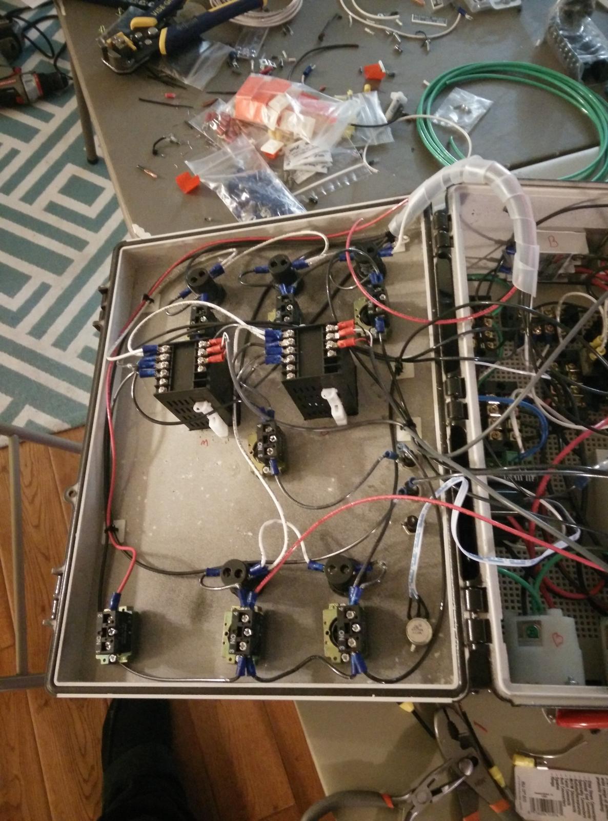
I merged a couple of PJ's diagrams together for my system and it tested flawlessly on first startup. Very pleased and very grateful for the work you have put in here. These pictures were progress photos, the wiring is cleaned up a lot better now.

IMG_20141110_212359.jpg


IMG_20141110_212236.jpg


IMG_20141110_212228.jpg
 
P-J, I just wanted to say thanks again for all your advice and detailed documentation you've provided. I wanted to speak with you prior to the BYO people reaching out to you but as I understand it they have already talked with you. I hope that it was no problem that your work will be published in an upcoming article, I was sure to give many thanks to you and I just wanted you to know it couldn't have been done without you. Hopefully you know what I'm talking about with regards to the article.
 
P-J, I just wanted to say thanks again for all your advice and detailed documentation you've provided. I wanted to speak with you prior to the BYO people reaching out to you but as I understand it they have already talked with you. I hope that it was no problem that your work will be published in an upcoming article, I was sure to give many thanks to you and I just wanted you to know it couldn't have been done without you. Hopefully you know what I'm talking about with regards to the article.
Trent (and PJ):

I might as well chime in here and come clean too - The editor of BYO ran your article and PJ's electrical diagram by me too asking for my opinion as I've worked with them in the past on various things.

Generally speaking I thought the article was well written and well thought out (good work). I told them that there are a few things I would have done differently, but that everyone has different needs. From a factual standpoint I didn't find anything "incorrect" about the technical things, which is of course good.

The only thing was I was leery with them including is how the e-stop is wired (shorting power to ground). I recommended that they leave that out as I feel it's an unsafe practice. She ran my thoughts past another electrical engineer who builds UL listed industrial control panels and he agreed with me so the diagram was changed. So you can blame me for that change. ;) At first I didn't think a wiring diagram was going to be included so I only recommended they drop the one or two lines in the write-up that explain how the e-stop works. But once the diagram was also sent to me some changes had to also be done to it (as PJ already knows as they contacted him for the edits).

Congrats to both of you on the write-up! It's slated for the Jan/Feb issue.

Kal
 
Trent:

I might as well chime in here and come clean too - The editor of BYO ran your article and PJ's electrical diagram by me too asking for my opinion as I've worked with them in the past on various things.

Generally speaking I thought the article was well written and well thought out (good work). I told them that there are a few things I would have done differently, but that everyone has different needs. From a factual standpoint I didn't find anything "incorrect" about the technical things, which is of course good.

The only thing was I was leery with them including is how the e-stop is wired (shorting power to ground). I recommended that they leave that out as I feel it's an unsafe practice. She ran my thoughts past another electrical engineer who builds UL listed industrial control panels and he agreed with me so the diagram was changed. So you can blame me for that change. ;) At first I didn't think a wiring diagram was going to be included so I only recommended they drop the one or two lines in the write-up that explain how the e-stop works. But once the diagram was also sent to me some changes had to be done to it as PJ already knows as they contacted him for the edits.

Congrats on the write-up! It's slated for the Jan/Feb issue.

Kal

Thanks Kal, I've been lacking in contacting everyone that helped in some form or another. I'm glad they spoke to you and got your input as well, you were definitely a source of inspiration to me.

With regards to the E-Stop I chose to defer to the experts in that matter as I knew there were many others who knew better than I so I'm glad that all worked out.

I saw a sneak peak of the article yesterday and am looking forward to receive the Magazine next month. This has been a work in progress for quite some time but I didn't want to say anything and jinx it until I knew it was really going to happen.
 
Trent (and PJ):
...

The only thing was I was leery with them including is how the e-stop is wired (shorting power to ground). I recommended that they leave that out as I feel it's an unsafe practice.

...
Just a very curious question for all to ponder:

How does a GFCI circuit breaker test button work?

The E-Stop only allows:

"EPO - wired to trip GFCI main circuit breaker
with small leakage current. ( 0.06A)"

Anyway, you all do as you wish. No problem here.

P-J
 
Just a very curious question for all to ponder:

How does a GFCI circuit breaker test button work?

The E-Stop only allows:

"EPO - wired to trip GFCI main circuit breaker
with small leakage current. ( 0.06A)"

Anyway, you all do as you wish. No problem here.

P-J

Nice Socratic method, lol. We have certainly beaten this issue to death before, so I will try not to do it again. The worst thing that can happen when wired correctly is that the GFCI fails and the estop doesn't stop. Test your GFCI before every brew session and it is highly likely to work. Other methods can work too. :)
 
Single Element BIAB 30A PID
Auberin-wiring1-a4-5500w-BIAB-30d6.jpg

Electrical noob question:
Where the feed comes in, I see there are 4 terminal strips, one for each wire. But what do the circles at each split throughout the diagram mean? How do I split the wires? Do I use another terminal strip or run separate wires from the terminal strips where the wires originally come in? What about the wires coming from the switches "X2" and "24" that combine into 1? Do I put another terminal strip there or is there a better way?
 
So you can do it any number of ways. You can run each wire independently from the terminal strips, or you can pull off anywhere else in the panel. For example, the X2 and 24 portion on the siwtch - just run a short jumper wire from X2 to 24, and then a second wire from either X2 or 24 to the outlet. The wiring diagram is conceptual in nature - the wiring can be run however you need, so long as the connections are made as shown on the drawing. As in, you can do the X2 and 24 switch wiring however, so long as you're not pulling a wire from all the way back at the panel (keep all downstream wiring downstream, all upstream wiring upstream, etc).

Hope that clears a few things up.
-Kevin
 
So you can do it any number of ways. You can run each wire independently from the terminal strips, or you can pull off anywhere else in the panel. For example, the X2 and 24 portion on the siwtch - just run a short jumper wire from X2 to 24, and then a second wire from either X2 or 24 to the outlet. The wiring diagram is conceptual in nature - the wiring can be run however you need, so long as the connections are made as shown on the drawing. As in, you can do the X2 and 24 switch wiring however, so long as you're not pulling a wire from all the way back at the panel (keep all downstream wiring downstream, all upstream wiring upstream, etc).


Hope that clears a few things up.

-Kevin


Makes sense now. Thanks.
 
Is there a wiring diagram for a 120 volt, 15 amp, single element, single pump panel using standard cheapo light switches? Would a contactor be necessary at the element? This is using a 5500 watt 240v element wired at 120v. I wasn't planning on an e stop switch but if it's necessary I'll certainly incorporate one.

Also, can anyone provide a link to the actual fuses used in some of these diagrams?

[edit] sorry! found one close enough in the mix on post 2. Still wondering about the fuses though.

This is the diagram that best suites me, only I'm building for RIMS. Can this diagram be rewired so that the element can't fire if the pump isn't switched on? The 4a fuse presents a problem, I assume it's bad practice to move it to the other side of the switch? Otherwise I would just move the fuse after the pump switch and run element power after the switch but before the fuse.

Auberin-wiring1-a4-2000w-BIAB-120V-A.jpg
 
You can run your two switches in series - switch one sends power to the pump and to the second switch. Switch 2 sends power to the heating element. Switch 2 can only turn on the element if switch 1 is turned on. You would need to make sure that switch 1 is rated for the combined amperage of the pump AND the heating element, as power for both will be flowing through it. Switch 2 only needs to be rated for the heating element. There are other more complicated ways you could set it up, but that's pretty much the easiest.

Go ahead and move the fuse after the switch, it will still function to protect the pump.

Fuses can be found quite easily at Radio Shack, including a variety of holders.
-Kevin
 
Opinions on this? Would you be comfortable with it?

This is for RIMS tube, heating element is 1375 Watts at 120v. Light switch, outlets, and wiring will be rated 20A for good measure.

Can a duplex light switch safely be wired in this manner or should I use two single switches?

Changes I made were removing the e-stop, removing the fuse to my pid, removing pid power switch, and moving the pump fuse to after the switch to allow the pump and element switches to work in series.

ESc2qD3.png


(edit) If the pump fuse blows the element could still be fired... Thoughts/solutions?
 
Back
Top