You are using an out of date browser. It may not display this or other websites correctly.
You should upgrade or use an alternative browser.
You should upgrade or use an alternative browser.
List of PJ Electrical Diagrams
- Thread starter OatStraw
- Start date

Help Support Homebrew Talk:
This site may earn a commission from merchant affiliate
links, including eBay, Amazon, and others.
Hey guys, i've been digging through this thread but haven't found what I need.
Does anyone have a 30a 5500 1 Element 1 PID 2 Pump Estop Diagram they could share with me?
Finally got a little time to complete a diagram for you.
As always click on the image to see and save a full scale diageam that is printable on Tabloid paper. (11" x 17")

I hope this helps you in your desired plan.
P-J
TNugent
Well-Known Member
P-J, just wanted to start by saying thank you once again. I've been reading so many of your previous posts and have been learning so much. Just when I felt I had a good understanding of 120v wiring I start looking into an electric brewery with 240v and it seems like that 1 extra wire/leg makes things 4x as complicated.
I know I had asked this of you before but then I went another direction, but now I'm back. If you have the time and can find the extra space in this diagram I would love to add:
1) A Keyed switch that powers on the BCS and nothing else (I have a separate/dedicated circuit breaker in my panel build for the BCS). and 2) A Keyed switch that turns on everything else.
Thinking out loud, would the "everything else" switch need to be wired to a relay that would then turn on power to the system since we're switching 30amps? How about the BCS switch, does it depend on the amps the switch is designed to handle and seeing as the BCS power supply looks like it's 1a, as long as the switch is rated for over 1a no relay would be required?

Thanks again for all the knowledge you've shared and thanks in advance if you are able to modify the diagram to include the 2 extra switches and necessary components.
I know I had asked this of you before but then I went another direction, but now I'm back. If you have the time and can find the extra space in this diagram I would love to add:
1) A Keyed switch that powers on the BCS and nothing else (I have a separate/dedicated circuit breaker in my panel build for the BCS). and 2) A Keyed switch that turns on everything else.
Thinking out loud, would the "everything else" switch need to be wired to a relay that would then turn on power to the system since we're switching 30amps? How about the BCS switch, does it depend on the amps the switch is designed to handle and seeing as the BCS power supply looks like it's 1a, as long as the switch is rated for over 1a no relay would be required?
Thanks again for all the knowledge you've shared and thanks in advance if you are able to modify the diagram to include the 2 extra switches and necessary components.
Loodachris
12th man loud and proud!
So I get my box all wired up using the 2 element rims diagram and go to plug it in and the gfci trips right away. Ok fine probably did some wiring wrong after a few homebrews then I decided to totally remove the estop and wires and that stopped the breaker from tripping but I still get no power. I'll go through it this week wire to wire but it also got me thinking does the box need to be grounded somehow? I see on kal's boxes he has them grounded but the diagram I am using does not show that. I only have the main wire going into the box to the terminal strip and that has a ground on it but that's it.
MyNameIsPaul
Well-Known Member
I finished up my RIMS box! I couldn't have done it without all the help I learned here. Thanks a ton to P-J for getting this figured out for me!
It's a 120V system, using a BrewHardware RIMS Tube. Auber 2352 controlling a 2000w Camco ULWD Element. I used Front Panel Express for my cutouts and a Hoffman 8-C812 box from Ebay (Got it for $21 plus shipping!)
I can't wait to brew now!


It's a 120V system, using a BrewHardware RIMS Tube. Auber 2352 controlling a 2000w Camco ULWD Element. I used Front Panel Express for my cutouts and a Hoffman 8-C812 box from Ebay (Got it for $21 plus shipping!)
I can't wait to brew now!
Which diagram are you using? With that info I might be able to help you.So I get my box all wired up using the 2 element rims diagram and go to plug it in and the gfci trips right away. Ok fine probably did some wiring wrong after a few homebrews then I decided to totally remove the estop and wires and that stopped the breaker from tripping but I still get no power. I'll go through it this week wire to wire but it also got me thinking does the box need to be grounded somehow? I see on kal's boxes he has them grounded but the diagram I am using does not show that. I only have the main wire going into the box to the terminal strip and that has a ground on it but that's it.
P-J


$53.24
1pc Hose Barb/MFL 1.5" Tri Clamp to Ball Lock Post Liquid Gas Homebrew Kegging Fermentation Parts Brewer Hardware SUS304(Liquid Hose Barb)
yunchengshiyanhuqucuichendianzishangwuyouxiangongsi


$44.99
$49.95
Craft A Brew - Mead Making Kit – Reusable Make Your Own Mead Kit – Yields 1 Gallon of Mead
Craft a Brew
![Craft A Brew - Safale S-04 Dry Yeast - Fermentis - English Ale Dry Yeast - For English and American Ales and Hard Apple Ciders - Ingredients for Home Brewing - Beer Making Supplies - [1 Pack]](https://m.media-amazon.com/images/I/41fVGNh6JfL._SL500_.jpg)
$6.95 ($17.38 / Ounce)
$7.47 ($18.68 / Ounce)
Craft A Brew - Safale S-04 Dry Yeast - Fermentis - English Ale Dry Yeast - For English and American Ales and Hard Apple Ciders - Ingredients for Home Brewing - Beer Making Supplies - [1 Pack]
Hobby Homebrew


$22.00 ($623.23 / Ounce)
AMZLMPKNTW Ball Lock Sample Faucet 30cm Reinforced Silicone Hose Secondary Fermentation Homebrew Kegging joyful
无为中南商贸有限公司


$33.99 ($17.00 / Count)
$41.99 ($21.00 / Count)
2 Pack 1 Gallon Large Fermentation Jars with 3 Airlocks and 2 SCREW Lids(100% Airtight Heavy Duty Lid w Silicone) - Wide Mouth Glass Jars w Scale Mark - Pickle Jars for Sauerkraut, Sourdough Starter
Qianfenie Direct

$176.97
1pc Commercial Keg Manifold 2" Tri Clamp,Ball Lock Tapping Head,Pressure Gauge/Adjustable PRV for Kegging,Fermentation Control
hanhanbaihuoxiaoshoudian

$53.24
1pc Hose Barb/MFL 1.5" Tri Clamp to Ball Lock Post Liquid Gas Homebrew Kegging Fermentation Parts Brewer Hardware SUS304(Liquid Hose Barb)
Guangshui Weilu You Trading Co., Ltd


$7.79 ($7.79 / Count)
Craft A Brew - LalBrew Voss™ - Kveik Ale Yeast - For Craft Lagers - Ingredients for Home Brewing - Beer Making Supplies - (1 Pack)
Craft a Brew


$10.99 ($31.16 / Ounce)
Hornindal Kveik Yeast for Homebrewing - Mead, Cider, Wine, Beer - 10g Packet - Saccharomyces Cerevisiae - Sold by Shadowhive.com
Shadowhive


$58.16
HUIZHUGS Brewing Equipment Keg Ball Lock Faucet 30cm Reinforced Silicone Hose Secondary Fermentation Homebrew Kegging Brewing Equipment
xiangshuizhenzhanglingfengshop


$20.94
$29.99
The Brew Your Own Big Book of Clone Recipes: Featuring 300 Homebrew Recipes from Your Favorite Breweries
Amazon.com


Loodachris
12th man loud and proud!

I am going back through all my wiring now. All the spots where I have to connect multiple wires together is where I think I got something mixed up. I figured it was all off one hot leg so I just kind of connected everything mixed up for some reason. Hopefully that was my problem and I'll just go back through and wire nut the right wires together this time and see what happens?
Please let me know what you find.I am going back through all my wiring now. All the spots where I have to connect multiple wires together is where I think I got something mixed up. I figured it was all off one hot leg so I just kind of connected everything mixed up for some reason. Hopefully that was my problem and I'll just go back through and wire nut the right wires together this time and see what happens?
P-J
Loodachris
12th man loud and proud!
Will do and thanks but what about the box being grounded? The only ground wire I have is coming from the main wire to the terminal strip is that enough?
The ground wire must go to the element shells, the pump outlets and also the controller box. Basically any metal in the system that you can touch during a brew session.Will do and thanks but what about the box being grounded? The only ground wire I have is coming from the main wire to the terminal strip is that enough?
I hope this makes sense.
Loodachris
12th man loud and proud!
Makes sense. I got 2 element kits that will be grounded to the box that houses the wires for the element so that's taken care of. Inside the box can I just run one of the wires from the ground terminal strip to the bolt that holds in on the box or is there a better or safer way?
jsguitar
Well-Known Member
That will work if it's bare metal and reliably connects to the rest of the box. The terminal strip in the drawing is really just for illustration. You'd normally use something like a grounding bar which is not insulated from the box to tie the box and all of your ground runs together.
Loodachris
12th man loud and proud!
That will work if it's bare metal and reliably connects to the rest of the box. The terminal strip in the drawing is really just for illustration. You'd normally use something like a grounding bar which is not insulated from the box to tie the box and all of your ground runs together.
Going to hit up Home Depot tomorrow and get one of those to finish this build off. After re doing all the 14g wires and adding a ground I went to the garage and plugged it in and again the breaker popped so I disconnected the E stop wires and plugged it in again and there we go the box works so I have no idea what is wrong with the e stop or maybe it's how I wired it but it keeps tripping the breaker. But now that it's on the PID's keep flashing random numbers and letters ( actually one says "oral" which is disturbing) at me so I connected one of the temp probes and that worked for the one. Now to finish my kegs and stand hopefully this weekend. Thanks for all the help here I could not of done it without you!

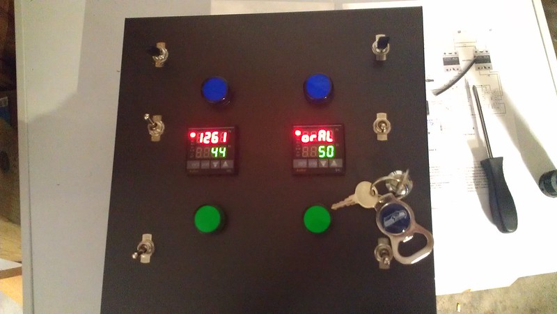
IMAG0202 by Ludahchris, on Flickr
jsguitar
Well-Known Member
Looking good!
Yeah the PID's flash like that without the probes.
What kind of switch are you using for the e-stop? I can't see it in your pic. It really sounds like you have that circuit wired so that it's always closed somehow.
Good luck!
Yeah the PID's flash like that without the probes.
What kind of switch are you using for the e-stop? I can't see it in your pic. It really sounds like you have that circuit wired so that it's always closed somehow.
Good luck!
Loodachris,
What are you using for your E stop? I do not see the switch on your panel picture. Is it possible that you are using a normally closed switch? (closed contact when not activated) If so that is the root of the problem.
What are you using for your E stop? I do not see the switch on your panel picture. Is it possible that you are using a normally closed switch? (closed contact when not activated) If so that is the root of the problem.
Loodachris
12th man loud and proud!
I put the E stop on top next to the heat sink but it's the Auber Instruments SW6 I think and looking at it now I had it connected to the NC side which would make sense. I probably just did all this rework for nothing. Pretty sure I won't mix home brew pints and electrical boxes anymore ")
Loodachris
12th man loud and proud!
Loodachris,
Wht are you using for your E stop? I do not se th switch on your panel picture. Is it possible that you are using a normally closed switch? (closed contact when not activated) If so that is the root of the problem.
Have you ever face palmed and felt like a knuckle head before? I just did! :smack:
Almfamily
Well-Known Member
Just finished reading through this entire thread as I am in the process of building an electric setup in my basement.
I just wanted to take a minute to thank PJ for all his time and effort to put all this together. And, the support you have given everyone throughout - simply amazing. I am likely going to be doing something very close to BNB's design, but a 30A. Looking forward to continuing to follow along with this thread!
I just wanted to take a minute to thank PJ for all his time and effort to put all this together. And, the support you have given everyone throughout - simply amazing. I am likely going to be doing something very close to BNB's design, but a 30A. Looking forward to continuing to follow along with this thread!
BadNewsBrewery
Well-Known Member
Good luck! If you run into any issues don't hesitate to PM me.
Almfamily
Well-Known Member
Good luck! If you run into any issues don't hesitate to PM me.
Thanks a lot - appreciate the offer! I may have a sparging question at some point...
OP
OP
OatStraw
Well-Known Member
OK I think I'm getting confused with 10/4 and 10/3 wire. Everything I've seen calls for 10/4 cabling from the source. Looking at what lowes sells as 10/3 comes with 4 wires including the ground.
This diagram from ebrew supply shows only 3 wires, not sure where the ground is supposed to go.
http://www.ebrewsupply.com/designs/PID/30a-PID-1-2-1PID-Electric-BIAB.pdf
To be able to put a 120v outlet in for a pump will that lowes 10/3 wire work, and is the ebrewsupply.com diagram correct?
This diagram from ebrew supply shows only 3 wires, not sure where the ground is supposed to go.
http://www.ebrewsupply.com/designs/PID/30a-PID-1-2-1PID-Electric-BIAB.pdf
To be able to put a 120v outlet in for a pump will that lowes 10/3 wire work, and is the ebrewsupply.com diagram correct?
OK I think I'm getting confused with 10/4 and 10/3 wire. Everything I've seen calls for 10/4 cabling from the source. Looking at what lowes sells as 10/3 comes with 4 wires including the ground.
This diagram from ebrew supply shows only 3 wires, not sure where the ground is supposed to go.
http://www.ebrewsupply.com/designs/PID/30a-PID-1-2-1PID-Electric-BIAB.pdf
To be able to put a 120v outlet in for a pump will that lowes 10/3 wire work, and is the ebrewsupply.com diagram correct?
the ground is on all the outlets. Your run the 10/4 into the enclosure and attach the ground to the grounding post. Then connect all the outlet grounds to that as well. Make sense?
rgauthier20420
Well-Known Member
- Joined
- Sep 20, 2012
- Messages
- 771
- Reaction score
- 70
Hello,
I'm going to be starting a simple build for a single element 120V RIMS unit and I'm trying to find a wiring diagram for this. I noticed in the 1st post there is one that includes an e-stop, which I won't be using, but I need basically the exact thing w/o the e-stop. I'm no electrical genius but I'm great at following diagrams/directions for this kind of stuff.
Any help is greatly appreciated!
Which specific diagram are you referencing? (Link?)Hello,
I'm going to be starting a simple build for a single element 120V RIMS unit and I'm trying to find a wiring diagram for this. I noticed in the 1st post there is one that includes an e-stop, which I won't be using, but I need basically the exact thing w/o the e-stop. I'm no electrical genius but I'm great at following diagrams/directions for this kind of stuff.
Any help is greatly appreciated!
I don't see one for RIMS only. I certainly can draw one for you.
rgauthier20420
Well-Known Member
- Joined
- Sep 20, 2012
- Messages
- 771
- Reaction score
- 70
Which specific diagram are you referencing? (Link?)
I don't see one for RIMS only. I certainly can draw one for you.
It isn't neccassarily labeled RIMS. It's the 120V single element diagram. I can't link the attachments from the 1st post on here, so here it is attached.
Edit: Oops, attached the wrong one. But this one might a little closer to what I'm attempting. Basically, my plans are for a single element, 3 switches (1 for the pump), single PID/SSR and no e-stop. All on 120V.
.jpg")
Hello,
I'm going to be starting a simple build for a single element 120V RIMS unit and I'm trying to find a wiring diagram for this. I noticed in the 1st post there is one that includes an e-stop, which I won't be using, but I need basically the exact thing w/o the e-stop. I'm no electrical genius but I'm great at following diagrams/directions for this kind of stuff.
Any help is greatly appreciated!
Ok. Here is a diagram that you can use.
As always click on the image to see and save a fullscale diagram for your build.

I hope this helps you.
P-J
MyNameIsPaul
Well-Known Member
Ran my PJ Inspired system for the first time yesterday. It's a thing of beauty!
rgauthier20420
Well-Known Member
- Joined
- Sep 20, 2012
- Messages
- 771
- Reaction score
- 70
Thanks so much P-J. That's pretty much what I'm picture it as. As usual, you are very fast with the diagrams. Excuse the "likely" noob questions, but are the contactors completely needed? Could the panel be wired w/o them? Safely....I should add. If the contactors aren't, then would I run the line directly into the box and just break of to how your diagram is wired?
Contactors??? The last diagram that I posted does not have contactors.Thanks so much P-J. That's pretty much what I'm picture it as. As usual, you are very fast with the diagrams. Excuse the "likely" noob questions, but are the contactors completely needed? Could the panel be wired w/o them? Safely....I should add. If the contactors aren't, then would I run the line directly into the box and just break of to how your diagram is wired?
Please explain.
P-J
rgauthier20420
Well-Known Member
- Joined
- Sep 20, 2012
- Messages
- 771
- Reaction score
- 70
Contactors??? The last diagram that I posted does not have contactors.
Please explain.
P-J
There it is...my noob understanding coming out. I'm referencing the three plates on the left hand side of the diagram.
Similar threads
- Replies
- 14
- Views
- 3K
- Replies
- 6
- Views
- 2K
- Replies
- 1
- Views
- 2K
- Replies
- 1
- Views
- 1K
