ITC-1000F Wiring Question

Homebrew Talk - Beer, Wine, Mead, & Cider Brewing Discussion Forum

Help Support Homebrew Talk - Beer, Wine, Mead, & Cider Brewing Discussion Forum:

This site may earn a commission from merchant affiliate links, including eBay, Amazon, and others.

msal

Active Member
Joined
Jan 31, 2012
Messages
28
Reaction score
4
Location
Effingham
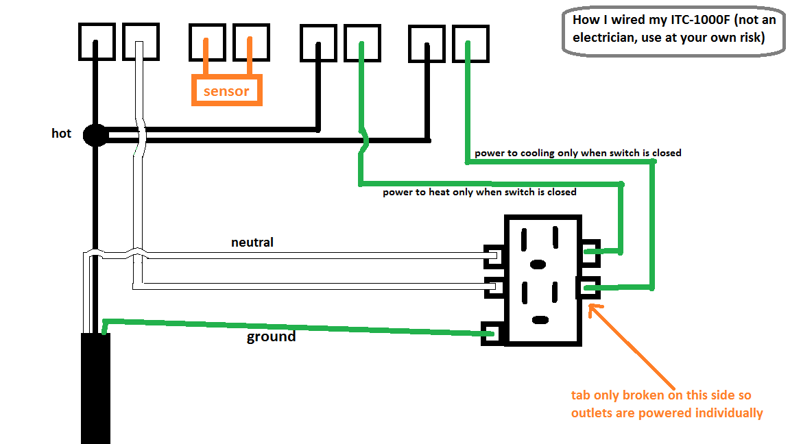
Hey all, I am in the process of wiring an ITC-1000F to use for fermentation temperature control. I'm a little bit hung up on the wiring diagram. It seems to contradict everything I am finding online, which is mostly for the STC-1000. I'm going for something just like this:


Here's a picture of the diagram on the controller itself:
http://imgur.com/lGKBTtH

Here's a wiring diagram from the amazon listing for the controller:
http://imgur.com/qX4hPDw

Most of the diagrams I've found online indicate that inputs 1, 5, and 7 should be hot, meaning I should splice my hot wire 3 ways and feed in to 1, 5, and 7. However, the diagram doesn't seem to match that. It looks like hot is going to 2, 5, and 7. Am I just mis-reading the diagram?

Based on the diagram, it looks like 6 and 8 should be going out to my cooling/heating element (in my case, to my outlet). This way, the wire heading to the cooling/heating element is only live when the switch is closed. If there is ever a short, the wires heading to the cooling/heating won't be live unless the switch is closed, right? This confirms my thoughts about hot going to 5, and 7 with hot at least.

I'm thinking I'm just fundamentally missing something in that diagram. Better safe than sorry!
 
Last edited by a moderator:
Both schematics are electrically equivalent. The STC-1000 and ITC-1000F are the same interface.

Here is a quick how-to guide assuming you are trying to make a controller similar to the youtube one with an ITC-1000F

Pieces:
power cable that has a 3-pin outlet (white, black and green).
3 white pieces of wire
5 black pieces of wire
2 large wire nuts
Outlet (be sure to break the bridge off the connects the 2 outlets together!)

Take the white wire from the power cable and the 3 white pieces of wire and connect them together via a wire nut.

Take the black wire from the power cable and 3 black pieces of wire and connect them together via a wire nut.

Connecting the white wires:
Connect 1 white wire to Pin 1 of the controller
Connect the white wires other 2 the outlet's white side (Maybe marked neutral)

Connecting the black wires:
Connect 1 black wire to Pin 2 of the controller
Connect 1 black wire to Pin 5 of the controller
Connect 1 black wire to Pin 7 of the controller

Connect the green wire to the green screw on the outlet.

2 Remaining black pieces of wire:
Connect 1 white wire to Pin 6 and the other side to one of the outlets (this is your heating outlet - make note of it).
Connect 1 black wire to Pin 8 and the other side to other outlet (this is your cooling outlet - make note of it).

Now connect the temperature sensor to pins 3 & 4 of the controller. Order does not matter here.

Now you are all set, test for shorts and functionality. If you do not have an outlet tester, use a lamp.

Good luck.
 
Both schematics are electrically equivalent. The STC-1000 and ITC-1000F are the same interface.

Here is a quick how-to guide assuming you are trying to make a controller similar to the youtube one with an ITC-1000F

Pieces:
power cable that has a 3-pin outlet (white, black and green).
5 white pieces of wire
3 black pieces of wire
2 large wire nuts
Outlet (be sure to break the bridge off the connects the 2 outlets together!)

Take the black wire from the power cable and the 3 black pieces of wire and connect them together via a wire nut.

Take the white wire from the power cable and 3 white pieces of wire and connect them together via a wire nut.

Connecting the black wires:
Connect 1 black wire to Pin 1 of the controller
Connect the black wires other 2 the outlet's black side (Maybe marked Hot)

Connecting the white wires:
Connect 1 white wire to Pin 2 of the controller
Connect 1 white wire to Pin 5 of the controller
Connect 1 white wire to Pin 7 of the controller

Connect the green wire to the green screw on the outlet.

2 Remaining white pieces of wire:
Connect 1 white wire to Pin 6 and the other side to one of the outlets (this is your heating outlet - make note of it).
Connect 1 white wire to Pin 8 and the other side to other outlet (this is your cooling outlet - make note of it).

Now connect the temperature sensor to pins 3 & 4 of the controller. Order does not matter here.

Now you are all set, test for shorts and functionality. If you do not have an outlet tester, use a lamp.

Good luck.

Before I saw this post I decided to go ahead and follow the STC-1000 video above. Everything appears to be working as expected. I'm relying on an outlet tester to verify that everything is correct, and I see the right combination of lights indicating no reverse polarity or any other problems.

It sounds like what I've done and what is done in the video are slightly different then what you are describing. Although things are working right, for peace of mind and in case anyone else stumbles on to this thread, I think it's worth investigating further. To me what I've done and what is done in the video does not match the diagram on the ITC-1000 itself at all (see original post), which is the biggest reason why I am still scratching my head.

Here is a rough diagram I've just created of how I wired things up, which is probably easier than describing it:
2asNCqu.png


Tofuguy, isn't what you are suggesting considered "switching the neutral" rather than "switching the hot" and typically advised against? I'm far from an expert so I might be mis-understanding something. To me it sounds like the devices will always be hot since the switch comes after them in the circuit.

Matt
 
You do bring a good point Matt. I will edit my post to avoid risk of others following it.
 
You do bring a good point Matt. I will edit my post to avoid risk of others following it.

Ok :). Thanks for the input by the way!

It's probably safe to say my wiring is OK as things are working fine. Hopefully this thread may help others out who are as confused as I was about the wiring diagram on the controller itself.
 
I've got the brains of my wine cooler bypassed and ran the sensor in through the top light hole, all ready to go... Time to test it out! I very quickly realized that the controller isn't reflecting the actual temp inside the fridge which is noticeably colder (confirmed this with a plain old thermostat sitting inside the fridge) :smack:. The controller just sits right around 69 degrees (room temp) despite what the sensor is returning.

I tested the sensor with my multi-meter at room temperature and after letting it sit in the fridge for a few minutes, and it seems to be working just fine.

Since I had the sensor disconnected, I decided to turn on the controller to see what would happen. According to the manual, you are supposed to hear an audible alarm when the sensor has a short circuit, open circuit, or if over temp. No alarms, no difference whatsoever. I see the exact same results with the sensor connected as when it's disconnected. The oddest part is that the temperature is fluctuating slightly, as though the controller has an internal temp sensor.

I'm going to try putting the entire controller in the fridge for a few minutes. I'm not sure who if anyone is reading this at this point, but maybe it will help someone later who is having similar problems.
 
Whole unit in the fridge still displays around 69 degrees. Very strange that the unit is 'stuck' near 69 degrees while still fluctuating somewhat (~1/2 a degree at most). Oh well, I guess it's time to RMA :(
 
Sounds like a soft short internal to the ITC-1000F.

Yup, agreed. Figures it resulted in a temp right around room temp :). I tested it immediately after wiring power to it and figured it was working fine since that was about my house temperature. Oh well, I should have a new one tomorrow via Amazon Prime :rockin:. I'll post a picture or two once I get the whole thing wired up.
 
Soo what's the right way?

The diagram I posted is correct as far as I know. I've built a second one since.you can pick up a nicer pre-built one for $35 nowadays so I'm not sure I would bother with the DIY route anymore.
 
Back
Top