• Please visit and share your knowledge at our sister communities:
  • If you have not, please join our official Homebrewing Facebook Group!

    Homebrewing Facebook Group

Input on Wiring Diagram

Homebrew Talk

Help Support Homebrew Talk:

This site may earn a commission from merchant affiliate links, including eBay, Amazon, and others.
...
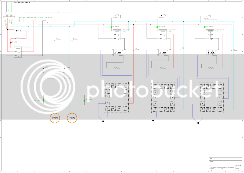
These pictured wiring diagrams are sometimes hard to read. For example, I can't tell exactly how your DPDT relays are wired. You have 6 terminals and 9 wires all on one relay. If you could please provide a little more detail so that we can give you better quality input.
I also find it difficult to follow.

Wonder if you could add another contact block on the 3way switch so the rims would only activate when the bk element is off,
You are right. (I think) Best I can figure the way it is now - The HLT and BK are interlocked. BUT - It is possible to fire the RIMS along with either the HLT or the BK. That's over 30A (not counting PIDS or pumps) with the BK and RIMS fired.
 
Sorry it is hard to understand. What I did was this:

-Two hot lines going in (red and black)
-Then I ran a line from the incoming black line to the switch which then goes back to the DPDT to control the open or close state of the switch.
-Added a neutral line since it will need one.
-after the DPDT I added two wires to an indicator light which will light up with the switch is open.
-then one hot line goes to the element and the other goes to the SSR which then goes to the element.

I did all this in photoshop which was rather painful but I tried to make it as organized as possible. The breakers replaced the blade style fuses I used in the original diagram.
 
Sorry it is hard to understand. What I did was this:

-Two hot lines going in (red and black)
-Then I ran a line from the incoming black line to the switch which then goes back to the DPDT to control the open or close state of the switch.
-Added a neutral line since it will need one.
-after the DPDT I added two wires to an indicator light which will light up with the switch is open.
-then one hot line goes to the element and the other goes to the SSR which then goes to the element.

That makes sense, but I usually see the SSR before the DPDT relay. What I mean by that is the SSR between the PID and the DPDT relay, instead of the SSR between the DPDT and the element. I suppose it doesn't really matter though... :confused:

Providing a better schematic would really help us with giving input and would really help you with troubleshooting any future problems. This is some dangerous stuff, so be as thorough as you can.

I did all this in photoshop which was rather painful but I tried to make it as organized as possible. The breakers replaced the blade style fuses I used in the original diagram.

Why the replacement?

I am not trying to bug you or anything. I'm just working on something very similar and also trying to understand all of it.

Wonder if you could add another contact block on the 3way switch so the rims would only activate when the bk element is off,

I'm conjuring up something to solve this problem. I want to use the MLT element in an ERIMS tube, while the HLT/BK elements are for EHERMS. I'll post what I come up with as soon as I can.
 
I was using WBerry's suggestion from the second post and added the breakers inside the box, however inline tube fuses were also suggested...and I may go that rout anyway.

I will work on tracking down actual diagrams for the different switches so that I can actually show where the wires will connect.

Look forward to seeing your solution to the 3 position switch issue. I was just going to make sure I was careful but it never hurts to build in something that mitigates user error.
 
CPanelDiag.png


http://i378.photobucket.com/albums/oo223/andersnelson/CPanelDiag.png

Ok here is my next crack at a cpanel diagram. Sorry about the SSR symbol...it was the only one that came with the program. I simplified this one again to make sure I had the fundamentals taken care of. I may try to add a three pos switch to only allow power to the BK element or the RIMS and the HLT elements. Ok, fire away.
 
Good catch!
Yes, the LEDs need to be in parallel rather than in series with the contactor coils.

I learned the hard way when I tested my newly finished control box. I couldn't figure why i wasn't getting enough power to the contactor until I measured the voltage after the LED. It dropped from 120 to 4 volts. The LED itself doesn't take much to light it so for 120v LEDs a resister is added. I didn't think of that. After some snipping of several zipties I got it wired correctly.
 
Nicely done! Do those LEDs need to be connected to neutral to energize?

Good catch!
Yes, the LEDs need to be in parallel rather than in series with the contactor coils.

Yes, parallel indeed, but I don't think that's what he was talking about actually. The LEDs you have for the pumps. They are connected to the hot line twice instead of the hot and the neutral.
 
Sorry for the late response. Yes I used TinyCad. It took a couple minutes to learn and then it was easy, and like EarthBound said...ITS FREE! Thanks Walker I will make sure to swap out one hot for the neutral.
 
Yes, parallel indeed, but I don't think that's what he was talking about actually. The LEDs you have for the pumps. They are connected to the hot line twice instead of the hot and the neutral.

Bua ha ha, how could I miss it? Geez! :cross:
 
Back
Top