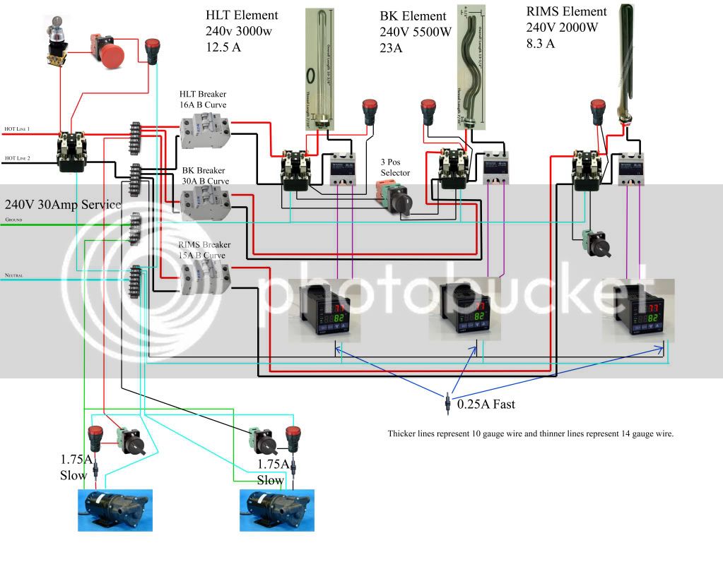
So I think I am ready to move from extract to AG and I am in the process of accumulating parts for a single tier electric setup. I was wondering if people would mind looking at the diagram I put together and let me know what I am missing or overlooking. There are a couple things to know about the diagram:
- Can I use the switches in between the PID and the SSRs to control when the PIDs are allowed to control the heating elements or should I just use them on the hot lines before the SSR?
- The BK PID is different because all I need is something to control the element manually and I thought I would save a few bucks...
- I am planning on using an inline GFCI breaker in my power cord.
- I was a little confused on fuse locations so I wanted to make sure those were in the right places.
- I didn't include the temp probes in this diagram so I know they are missing.
Anyway, any advice would be appreciated. Thanks and Cheers!
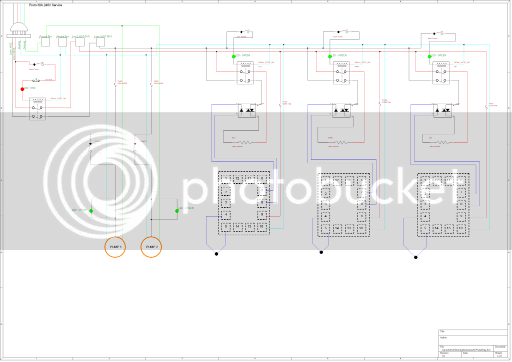
Newest diagram at post #37
- Can I use the switches in between the PID and the SSRs to control when the PIDs are allowed to control the heating elements or should I just use them on the hot lines before the SSR?
- The BK PID is different because all I need is something to control the element manually and I thought I would save a few bucks...
- I am planning on using an inline GFCI breaker in my power cord.
- I was a little confused on fuse locations so I wanted to make sure those were in the right places.
- I didn't include the temp probes in this diagram so I know they are missing.
Anyway, any advice would be appreciated. Thanks and Cheers!
Newest diagram at post #37