Illuminated Rocker Switch DPST Wiring

Homebrew Talk - Beer, Wine, Mead, & Cider Brewing Discussion Forum

Help Support Homebrew Talk - Beer, Wine, Mead, & Cider Brewing Discussion Forum:

This site may earn a commission from merchant affiliate links, including eBay, Amazon, and others.

Surfmase

Well-Known Member
Joined
Mar 29, 2016
Messages
50
Reaction score
13
Location
Zürich
Hello,

I'm in Europe with 240 V mains. I'm not certain, but I think it is correct to call the blue wire "load", the brown wire "neutral", and the green/yellow wire "protective earth". For each heating element I'm using an illuminated DPST illuminated rocker switch combined with a SSR. I wanted to have the switch LED light up when the SSR is powering the heating element. As I have it now, the switch LED illuminates whenever the switch is closed. The SSR is switching the heating element as desired, but this has no effect on the switch led.

I have the blue wire going first to the SSR and then to one pole of the switch and from the switch to the outlet for the heating element. I have the brown wire going to the other pole of the switch and from the switch to the outlet for the heating element. The yellow/green wire goes directly to the outlet for the heating element.

edit: On the other hand I have the same switches on both my pump and HLT mixer. In these cases there are no relays, there is only this switch between mains and the respective outlet and I am switch both brown and blue wires on each of the 2 poles. Here the switch is constantly illuminated regardless of it's position. The pump and mixer operate properly when the switch is closed.

What am I missing?

Thanks for your help
 
Last edited:
I'm in Europe with 240 V mains. I'm not certain, but I think it is correct to call the blue wire "load", the brown wire "neutral", and the green/yellow wire "protective earth".
No. A quick Google search (I'm in the US, so more familiar with NEC color coding) shows IEC color coding has blue for neutral and brown for line, so you have that backwards, which could mean you have things wired dangerously.

As I have it now, the switch LED illuminates whenever the switch is closed.
What do you mean by closed? In electrical parlance, "closed" means power is flowing, open means power is not flowing.

What type of switch are you using? Are there terminals for the light? In my experience with lit switches there are usually terminals specifically for the light so it can be wired as desired for whatever operation.

Do you have a schematic of how this is wired? Or at least pictures? Either would be great, I'm having trouble following yiur discription alone, especially as I don't know how your particular switches are laid out and internally wired for the light.
 
Hi, thanks for the reply,

I may have the colors backwards, but in my box the blue bank has 230V and the brown doesn’t.
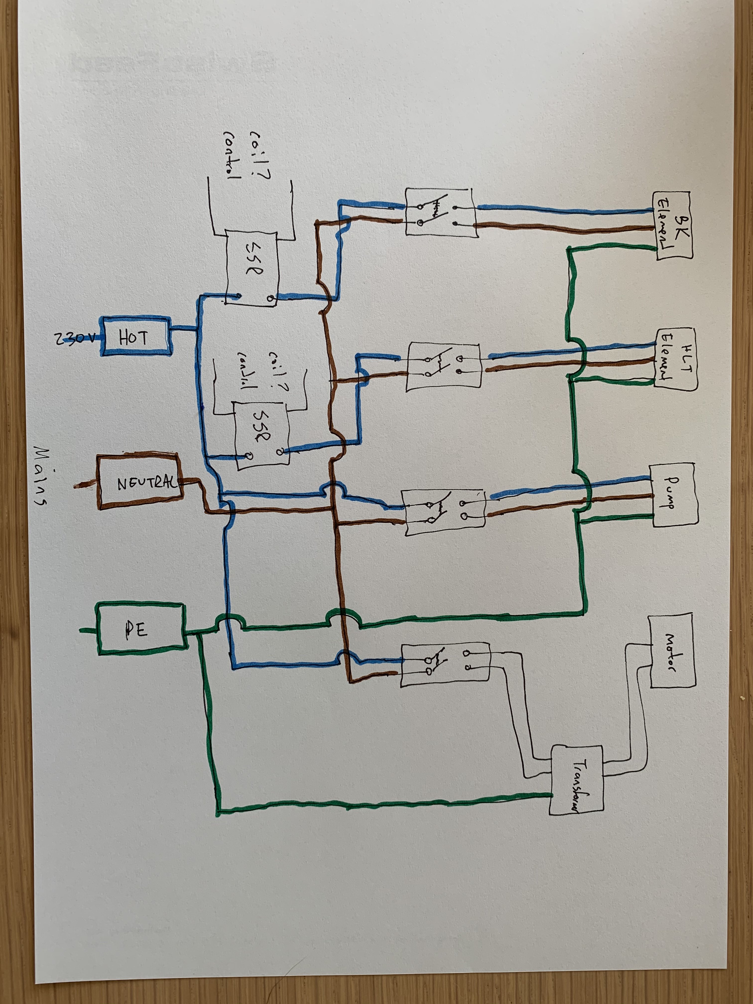
Here is a picture of the diagram.
99C3365C-EE23-40D4-A9A8-3E859235629A.jpeg


I believe this is the switch. There are only 4 terminals.

https://www.distrelec.ch/en/rocker-switch-dpst-16-on-off-black-green-bulgin-c1353algne/p/30013159
yes, closed as in electrical parlance “closed”, as in I not O on the switch Pictogramm.

thanks,
 
I'm in Europe with 240 V mains. I'm not certain, but I think it is correct to call the blue wire "load", the brown wire "neutral", and the green/yellow wire "protective earth". For each heating element I'm using an illuminated DPST illuminated rocker switch combined with a SSR. I wanted to have the switch LED light up when the SSR is powering the heating element. As I have it now, the switch LED illuminates whenever the switch is closed. The SSR is switching the heating element as desired, but this has no effect on the switch led.
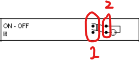
Ah, this is what I get for reading your message too early in the morning. You want the LED to illuminate when the SSR is on, not when the switch is on. Unfortunately, it appears independent operation of the LED on your switch is not possible, as the LED is hard-wired internally the switch on the 1353 model switches.
1602169958073.png


According to that diagram from the switch datasheet, the LED will always be on when the switch is on. Other switches I've seen tie the LED to seperate terminals, allowing you to wire it with the switch, opposite the switch, or to something unrelated, like an SSR turning on and off, but this does not appear to be such a switch.

edit: On the other hand I have the same switches on both my pump and HLT mixer. In these cases there are no relays, there is only this switch between mains and the respective outlet and I am switch both brown and blue wires on each of the 2 poles. Here the switch is constantly illuminated regardless of it's position. The pump and mixer operate properly when the switch is closed.
That sounds like you flipped the wiring of mains side and load side on the switch. I'm not certain what numbering your terminals have, but reference this switch in the diagram again. If you connect the brown and blue wires on the mains side to pair 2, and the pump to pair 1 (as I've labeled below), the light will always be on.
1602170352404.png

If instead the mains side is on pair 1, and the load on pair 2, then the LED will light as the switch is turned on and off. Compare the switch with the backwards LED to the switch providing power to the SSR, since that one seems to be wired how you want the pump LEDs to work.

I may have the colors backwards, but in my box the blue bank has 230V and the brown doesn’t.
In your brewing control box? How is that powered, a line cord to a standard receptacle? I'd double check the source if I were you, something doesn't sound right. Here in the US, I've seen outlets wired with the neutral and hot backwards, probably done by someone who isn't an electrician and didn't know how to check the outlet after install to verify proper wiring.
 
Wait, you're switching after the SSR. The light should be turning on and off with the SSR, even though it's hard wired. I've gotta think about this some more, but I need to get some work done first. I'll ponder some more.
 

What are your element wattage? This switch rated for 16Amp but I wouldn't trust it. I had a lot's of issue with this type of switches. Even a good ones OK only under 10-12Amp load. Bad one can start melting under 5Amp load. If you disassemble it you can see how thin contacts are. The good news- when it start melting it breaks circuit fast enough to not catch a fire (have 5 failed switches)
 
Fhe only thing that's come to mind all day about why the LED is always on for the switch on the SSR is leakage current through the SSR may be enough to light up the light.

Yes, SSR leakage current is small but enough to lit LED when heating element is disconnected. If element is connected lights should go off when SSR disengaged. You can connect a incandescent lite bulb instead of element for testing (don' use LED or CFL lamps )
 
Yes, SSR leakage current is small but enough to lit LED when heating element is disconnected. If element is connected lights should go off when SSR disengaged. You can connect a incandescent lite bulb instead of element for testing (don' use LED or CFL lamps )
Ah, that makes sense. The OP could have been testing it with the heating element disconnected.
 
Thanks for everyone’s input. Originally I had the switch connected before the SSR. As you pointed out, depending on which side I connected the mains, the led is either always lit or when the switch is on. Then I put the SSR before the switch hoping to see the element activity in the led. But yes I tested this with the element disconnected.

Im the one who wired the supply plug wrong. Somehow I got the colors switched. Nonetheless Im switching the load and not the neutral. Do you see anything unsafe with this diagram? Otherwise it’s only color nonconformity.

the elements are 2800 watt. I’ve used the system (before this rewire) for about 2 years now without problem. Maybe I’ll look at changing them out.

thanks again
 
Others pointed out that the SSR will leak enough to light the LED. It is also important to know which terminals the LED is hooked up to internally, which should be in the data sheet. You want to hook up the switch so the LED is on the element side of the switch. Otherwise it will light up whether you have the element plugged in or not. You may need to swap the wires on the switch to make this happen.
I have seen some designs that resorted to having both a contractor and an SSR in order to ensure the light goes out even with no element, but that is pedantic/anal/silly.
I would also make sure you use GFCIs and have a big red kill switch.
 
Back
Top