How to build a Brewing Control Panel - HERMS 240V 30 AMP

Homebrew Talk - Beer, Wine, Mead, & Cider Brewing Discussion Forum

Help Support Homebrew Talk - Beer, Wine, Mead, & Cider Brewing Discussion Forum:

This site may earn a commission from merchant affiliate links, including eBay, Amazon, and others.

MikeSkril

Well-Known Member
Joined
Feb 5, 2015
Messages
401
Reaction score
82
Hi,

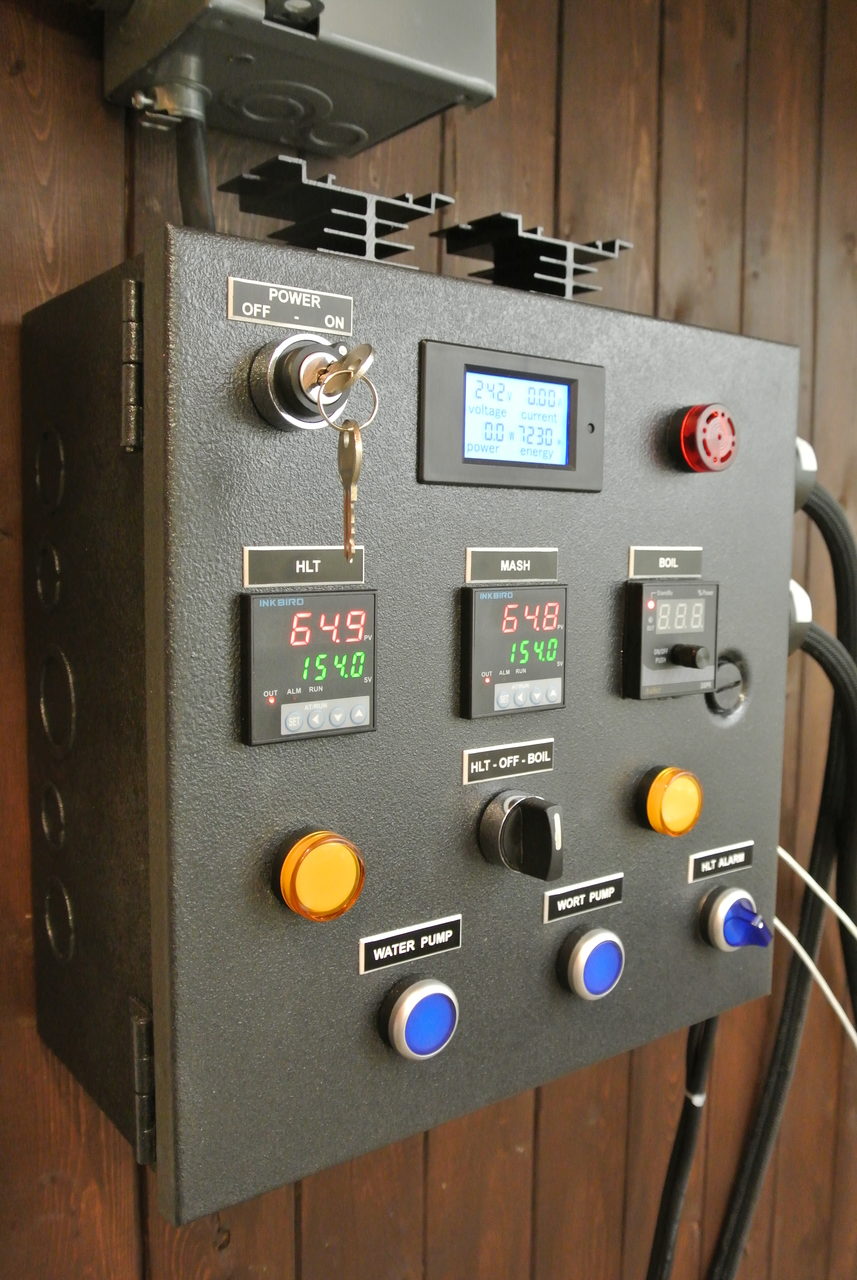
I finished my control panel a while ago. Just wanted to share the 'How To' I've made.

DSC_5434-e1489023520499.jpg


Feedback is always welcome!

https://skrilnetz.net/how-to-build-a-brewing-control-panel-herms-240v-30-amp/

The panel in action:

Prost!

DSC_5318.jpg
 
Last edited by a moderator:
This is exactly what I was looking for! Thank you! What would you guess the total cost of the project was?
 
This is exactly what I was looking for! Thank you! What would you guess the total cost of the project was?

I did not count. Just look up the parts and add $40 for wires, connectors,...
Somewhere in $500 I would say.
 
Excellent work!

Very well written and photographed, thank you. I am sure this will help many people with their designs and builds.
 
Wow, it's really good work. Thanks for sharing, will be using this for my build (a bit different since I use a main switch rater for 40A rather than switch + conductor).
 
Excellent! I just mounted my components in the exact same configuration (minus the voltage meter) and just haven't wired it up yet. Very clear now!
 
Excellent! I just mounted my components in the exact same configuration (minus the voltage meter) and just haven't wired it up yet. Very clear now!

Cool! Let me know if you have any questions.
 
I have been thinking about going this route, but haven't had a clear way to do it. After doing some more reading, I plan to do this! Thanks for the details.

BTW - where did you get your temperature probes?
 
Excellent work and precise documentation! Thanks for the share.

I went out on a limb when building my panel. To simplify construction and SSR/heat sink mounting, I sandwiched the SSR and heatsinks around the panel. Therefore heat flows from SSR through panel wall and into heat sink. Brewed at least 20 times without issue.
 
To simplify construction and SSR/heat sink mounting, I sandwiched the SSR and heatsinks around the panel. Therefore heat flows from SSR through panel wall and into heat sink. Brewed at least 20 times without issue.

I was thinking about that too, but I was afraid getting the heat out.
 
Hi MikeSkril

Thanks for this awesomeness!

I have one question regarding the CFGI..

You say "A GFCI protected source is mandatory if you want to live a long and happy life. You can use a GFCI breaker in your main electric panel, but a SPA panel with GFCI breaker will most likely be cheaper."

Can you tell me what a SPA panel with CFCI breaker is and how to put it together?

Thanks again!
 
Could you use the build with 20 gallon kettles?

20 gal batches or kettles?

I've used 15 gal kettles and 20 gal kettles would work too. I think if you want to make batches bigger than 10 gal, you want to build something with more power.
 
Hi MikeSkril

Thanks for this awesomeness!

I have one question regarding the CFGI..

You say "A GFCI protected source is mandatory if you want to live a long and happy life. You can use a GFCI breaker in your main electric panel, but a SPA panel with GFCI breaker will most likely be cheaper."

Can you tell me what a SPA panel with CFCI breaker is and how to put it together?

Thanks again!

A spa panel is normally used for hot tub installations. It's just an electrical box with a GFCI breaker. So you install a normal breaker in your main electrical box and run the wire to the spa panel, from there you run the wire into the control box.

You could also directly install a GFCI in your main panel. Just check whats the cheaper options. It depends on you main panel. The GFCI breaker for my main panel would have been $250, so I was glad finding a used spa panel for around $80. It does exactly the same job.

http://www.homedepot.com/c/steps_to_install_spa_panel_HT_PG_EL
 
You my friend are a master!! Great build and great write up on the process. I converted to electric and have a little more confidence after wiring my own portable GFCI spa panel with a still dragon potentiometer kit for my initial work up. I totally agree with you on the gaining electrical confidence. My box is simple now, it works, and I'm proud to say I did it (from the kit and the help of some of these great forum folks - of course!!) Your write-up has my wanting to take my panel to the next level and I will work it in to the grand planning of my brew budget dollars. Thanks again for this awesome write-up and detailed tutorial. I will be using it as my guide soon and appreciate the "giving back" by so many on this board.

Cheers [emoji482]

Thanks for the flowers! Everything is more fun when you share it with others! :mug:
 
Should the Inkbird ITC-106VH come with k sensor and solid state relay or just the pid?

Is there anything that you would change if you had to do it again?

I just had the spa panel installed by a professional. I like your set up. I keep researching and coming back to your design. I was talking about 20 gallon kettles in the previous posting. I really appreciate you posting and taking the time with the web page.
 
Last edited:
Should the Inkbird ITC-106VH come with k sensor and solid state relay or just the pid?

Is there anything that you would change if you had to do it again?

I just had the spa panel installed by a professional. I like your set up. I keep researching and coming back to your design. I was talking about 20 gallon kettles in the previous posting. I really appreciate you posting and taking the time with the web page.

I’ve bought the bundle with K-sensor (which I don’t use) and the SSR. You’ll need an SSR and if the price is right, go for it. Expect some long delays when buying stuff that ships from China!

I would not change a thing so far. Everything is working as expected. One can say that the Mash PID is not needed, but I like to see the mash temperature on the panel just right beside the HLT temperature.
Depending on your setup, the mash temperature can be a little lower than the HLT temperature. That’s because you are most likely loosing some heat on the way.
The alarm is a question of preference. I like to fill the HLT, set the temperature and go away for 45 minutes. The alarm calls when temperature is reached. The rest of the time I stick around anyway.

Anything you need, let me know!
 
The ROK Digital Multimeter AC 80-260V 100A has two different options 100A closed current transformer or 100A open close current transformer?

How did you come up with the exact size to cut for each component? I know some size like the alarm is 12mm. Did you just trace it on the enclosure.


I really appreciate your help?
 
The ROK Digital Multimeter AC 80-260V 100A has two different options 100A closed current transformer or 100A open close current transformer?

Not sure...I've used this one:
https://www.amazon.ca/DROK-Multimeter-Amperage-Measuring-Transformer/dp/B014W3D1OC

How did you come up with the exact size to cut for each component? I know some size like the alarm is 12mm. Did you just trace it on the enclosure.

Once I've got the multimeter, I've measured it and cut the hole with a jigsaw. I had to work the hole with a metal file till it I got a good fit.

The PID's have a standard hole size and the round components too (step drill is perfect for that).
 
Last edited by a moderator:
I got everything cut out and mounted the heat sinks today. I got a question for you about the heating elements. It is hard to find the Camco model 2965 ULWD element. It seems that when you search it the 2963 comes up. Do you know if that one would be acceptable?
 
I am at the wiring phase. Why do you have a jumper on your push button switch and the alarm switch. I don't see it in the diagram. Is jumped between 23 and 13 or 24 and 14. I order from the same spot but the back of my push buttons look a little different.

I am getting done slowly. I really appreciate your help.

The jumpers are to provide switched power to the LED lamps in the switches (the center blue blocks in the middle of the two black switch blocks. They are shown in the diagram.

Brew on :mug:
 
The jumpers are to provide switched power to the LED lamps in the switches (the center blue blocks in the middle of the two black switch blocks. They are shown in the diagram.

Brew on :mug:

Thanks, I ordered from the same site but the switches backs are different. Which would I jump on this switch? I really appreciate you help. I am trying to do as much as possible so when the electrician comes hopefully it will be cheaper. I only want to light up when engaged.
http://www.auberins.com/images/Manual/SW1_manual.pdf
 
Last edited:
Thanks, I ordered from the same site but the switches backs are different. Which would I jump on this switch? I really appreciate you help. I am trying to do as much as possible so when the electrician comes hopefully it will be cheaper. I only want to light up when engaged.
http://www.auberins.com/images/Manual/SW1_manual.pdf

The lamp is still the middle pair of terminals. Jumper one of the middle terminals to the load side of one of the outer blocks that is switching a hot line. The other middle termial connects to neutral.

Brew on :mug:
 
If you'll use male connectors on the panel (like I did), you'll need female connectors on the cable.

This would be the cable option to use:
Braided Cable with XLRCON-M connector (Male Panel Mount)
 
I finally finished everything had the electrician come out last night. The thing fired up like a champ. Everything worked correctly besides the switch between the two elements. They both stay on no matter the position of the switch. I checked the diagram over and over. I am not sure how this possible. The electrician did not see the error as well. He told me he is more of just a house electrician. Does anyone have an idea how I could have done this? The LED for elements correctly switch with the switch.
 
I finally finished everything had the electrician come out last night. The thing fired up like a champ. Everything worked correctly besides the switch between the two elements. They both stay on no matter the position of the switch. I checked the diagram over and over. I am not sure how this possible. The electrician did not see the error as well. He told me he is more of just a house electrician. Does anyone have an idea how I could have done this? The LED for elements correctly switch with the switch.

If both elements are on, why aren't you tripping the breaker (assuming 30A breaker)? Or, are you on a 50A breaker? Are you testing with the elements connected, or just using a voltmeter to test the element outlets? You need to have a load on the SSR's to test their switching. This is because SSR's have a small leakage current when off, and a high impedance voltmeter will see the full switched voltage with even a few microamps of leakage.

Brew on :mug:

It is a 40amp breaker. I didn't have the elements attached last night. The electrician had a pin that lights red when it detected volts. I will test again when I have everything connected. I really appreciate the help. It won't be for another two weeks. I got my last two pots coming in Monday and I have to solder the fittings. Thanks again, I will let you know.
 
If both elements are on, why aren't you tripping the breaker (assuming 30A breaker)? Or, are you on a 50A breaker? Are you testing with the elements connected, or just using a voltmeter to test the element outlets? You need to have a load on the SSR's to test their switching. This is because SSR's have a small leakage current when off, and a high impedance voltmeter will see the full switched voltage with even a few microamps of leakage.

Brew on :mug:

If he did wire like in my instructions, there will be no leaking to the element outlets. If the selector switch is OFF, current can leak to the contactors but no further. So if all is wired they way it should be, there will be no current on the receptacles when the selector switch is in OFF position.
 
It is a 40amp breaker. I didn't have the elements attached last night. The electrician had a pin that lights red when it detected volts. I will test again when I have everything connected. I really appreciate the help. It won't be for another two weeks. I got my last two pots coming in Monday and I have to solder the fittings. Thanks again, I will let you know.

Get a multimeter! They are pretty cheap and very helpful for troubleshooting.
 
Back
Top