• Please visit and share your knowledge at our sister communities:
  • If you have not, please join our official Homebrewing Facebook Group!

    Homebrewing Facebook Group

Home made peristaltic pumps

Homebrew Talk

Help Support Homebrew Talk:

This site may earn a commission from merchant affiliate links, including eBay, Amazon, and others.
Good news! My mate comes back from Mexico tomorrow and so things should get going on the MK 2 pump very soon. (once I've stopped playing with my new burners that is!)

Wow JVD, at those high revs your pump uses, the tube fails quite quickly! Is the tube silicone tube like the stuff we use, or is it special for that pump, as it looks to be black in the link. I am hoping that using silicone tube, and at my much reduced rpm of only 50 rpm the tube will last more like months, but we will only truly know after......err......months! Your pump makes the tube bend quite drastically around the rollers compared with squeezing it gently against an outer wall. My tube spec says it is ideal for use in perastaltic pumps, so my hopes are at least based on some sound info.
I will fit an hour meter to my pump so it's run time can get logged, and will keep my fingers crossed. Mind you, I've got to make it first!!!

How do you run your pump? Do you slow it down for variable flow rates?
 
Wow JVD, at those high revs your pump uses, the tube fails quite quickly! Is the tube silicone tube like the stuff we use, or is it special for that pump, as it looks to be black in the link.

No - I replaced the tubing with food grade silicone tubing.

How do you run your pump? Do you slow it down for variable flow rates?

I just run the pump at normal rates and use a valve to control the flow rate. Usually though, 2 GPM is not quite fast enough. I wish I could circulate faster.
 
Using a complete front drum with hub assembly including the tapered bearings then all you would need is a machined center axle that fits the two different cone bearing bores for a concentric mounting point for your roller spider to mount onto. Threaded axle with jam nuts for slight bearing preload. With the drum mounted on a bracket off the hub lug studs it would then be easy if you have the axle extended past the outboard side of the hub for a connecting means to a 90 VDC gearmotor with speed control. For holding the tubing in their channels or pockets machine oversize aluminum rings with the proper spacers, freeze the rings or use dry ice then install the rings. Once expanded into the drum remove the spacers between the aluminum rings these channels for your tubes to set in. Like you mentioned before, cut away what's needed to pass the tubing in and out of the drum which can just be holes in the channels angles into the direction of the tubing and radiused to prevent any tube chafing. building the pump body this way 90% of it is from a automotive breaker just pick the diameter drum you want, make the spider to your drum and rollers as well the aluminum rings. Surely those tapered greased wheel bearings will outlast a lifetime of use going from 1,000 pounds plus loading to almost zero bearing loading just rotating. This is how I would build one as there are many drums available at 12" ID and smaller, my lathe can only swing 12" for the aluminum tubing support rings. I would build it to allow for grease seals at both ends of the hub.


One could conceivably reverse the brake drum and keep it bolted to the truck axle permitting the truck to power the pump. The truck transmission would give you the added benefit of speed control. A diesel rig would probably be the most economical to operate.
 
JVD, Just in case you don't know this, you CANNOT close off the flow of a perastaltic pump like you can on the March type pumps. When you throttle back the flow, you need to provide somewhere for the restrained flow to escape, like back to wherever it came from via a return route fitted somewhere between the pump output and your restricting valve? If not, then your pump will over pressurize the tube and that may be the reason you are getting tube failures. To reduce the flow you should reduce the rpm, or change the tube for a smaller diameter bore, or throttle the output but provide a feedback route.

Catt 22 :- The thought of leaving the brake drum connected to the vehicle had not actually occurred to me! Do you lot (over there) realize how much we have to pay for fuel over here!!! It's a bloody good job my car averages 107 MPG to work, with 70 MPG around town. On good days it gets over 120! My record is 125.3 ( Note :- That's our gallons in a 2001 Honda Insight Hybrid )
 
Just found this thread and I am impressed. I am also inspired. I've done a good bit of work with miniature peristaltic so I know a little bit. I also have access to good CAD software and am pretty good with it. I will see what I can come up with this weekend if I have some time and post it on the board. I've got tons of ideas spinning in my head.
 
Nice to have another CAD savvy person on board! (the other one isn't me by the way)

What is it with Austin? Every other brewer on this forum seems to live there! Does Texas have some massive beer tax, or is it just a town with lot's of sensible people:drunk:
 
Well, one, we have a big beer drinking community with several local microbreweries and brewpubs who are involved in the community and we also have several really good beer bars. The culture in Austin is very focused around going out to eat and going out to bars. We also have one of the best LHBSs in the country. Aside from that, the people here are just generally awesome.

If anyone needs any help with any CAD work, I'd be glad to oblige. I enjoy doing it.
 
On the throttling the pump thing, you could throttle the flow to the intake of the pump, and as someone pointed out a while back that would just cause the tube to flatten if the pumps flow rate outstripped the actual supply. Still not good, but not too damaging either.
 
On the throttling the pump thing, you could throttle the flow to the intake of the pump, and as someone pointed out a while back that would just cause the tube to flatten if the pumps flow rate outstripped the actual supply. Still not good, but not too damaging either.

How about a different hose with thicker walls so you have a smaller id and therefore less flow?

-OCD
 
JVD, Just in case you don't know this, you CANNOT close off the flow of a perastaltic pump like you can on the March type pumps. When you throttle back the flow, you need to provide somewhere for the restrained flow to escape, like back to wherever it came from via a return route fitted somewhere between the pump output and your restricting valve? If not, then your pump will over pressurize the tube and that may be the reason you are getting tube failures. To reduce the flow you should reduce the rpm, or change the tube for a smaller diameter bore, or throttle the output but provide a feedback route.

I restrict in front of the pump - coming from the mashtun.... but I had never done it on the output side so that is great to know.
 
On the throttling the pump thing, you could throttle the flow to the intake of the pump, and as someone pointed out a while back that would just cause the tube to flatten if the pumps flow rate outstripped the actual supply. Still not good, but not too damaging either.

The tube flattens anyway...
 
Sorry about the slow progress! I have been concentrating on extending my outbuildings to make room for the the brewery, but the pump is coming along! I have now machined two 10 mm thick Perspex end plates for the 12" alloy tube and these contain the shaft bearings. Next I need to cut holes in the alloy tube for entry and exit points for the 1/2" silicone tube.

I have also completed my wort cooler project, which has six separate 16 ft long copper coils, made from 1/2" diameter pipe. Each coil is fed cold tap water and they are all suspended from a perspex lid. I am not posting details of that untill it is fully tested and I can give operational details and cooling performance figures. Suffice to say it is all plumbed up and does not leak when tap water flows through it at 15 litres per minute. It is a monster!
 
I have also completed my wort cooler project, which has six separate 16 ft long copper coils, made from 1/2" diameter pipe. Each coil is fed cold tap water and they are all suspended from a perspex lid. I am not posting details of that untill it is fully tested and I can give operational details and cooling performance figures. Suffice to say it is all plumbed up and does not leak when tap water flows through it at 15 litres per minute. It is a monster!

Wow! You are using 96 ft of 1/2" copper pipe! I don't think I could fit that much copper tubing inside my kettle and still have room for the wort. What kettle size are you planning to use with it?
 
I shouldn't be talking about this as it is off topic, but, the coils displace 1 imperial gallon, and are in a 22 imperial gallon stainless pot 18" diameter, 21" deep. I will post details, pictures, and a "how to" in the DIY area in a few weeks when I get my computer back from brain surgery.....It is reasonably easy to do.....make a wooden former, fill the copper tube with dry sand, bend tube into left hand and right hand pairs, fit any number of pairs to a stout lid (I made eight coils, but may settle on using just six) The coils intertwine, but do not touch, and are supported only where they come through the 10 mm thick lid using "cable glands" that compress a rubber sleeve onto the tube and clamp it firmly in place. I thing peeps will be suitably impressed once it is posted! Bear with me........
 
Today I cut the first of the three windows in the side of the aluminium tube, and fitted one of the silicone tubes inside for the first time! I will probably get to test for water pumping and priming tomorrow, or very soon, and then fit the other two tubes.
 
I have just run the Mk2 pump for the first time and it was a resounding success!!!

With the pump connected to my lathe so it was just above stomach height, I ran the lathe at 20 RPM, which is very slow indeed! The pump proceeded to start pumping the air in the pipe and water rose from floor level to the pump at a nice steady rate. This is the slowest I am likely to run the pump, so it has proven itself to be self priming at all speeds, as even the MK1 pump primed satisfactorily at higher speeds.

I now have to concentrate on enlarging the guide ways that I have positioned each side of the three pump tubes, and refining the inlet and outlet guides, as the pipes were tending to creep into the pump cavity as the wheels rotated!

Once I have fettled it a bit and made a proper mounting for it I will post pictures and maybe even a video!

I am now one step nearer to a working brewery!!!!!
 
Based on using my peristaltic during mashing I would suggest you pair the pump with a grant and either a direct heat mash tun or a HERMS system. A peristaltic pump does not work well in a RIMS configuration because it is likely that the mash will - at one time or another as I have experienced - create a stuck mash or vacuum, which causes the pump to flatten the hose, which in turn cuts off the flow to the RIMS, which in turn causes the heating element to melt.
 
I just bought a load of homebrew gear from a guy getting out of the hobby, and one gem was this blue motor and gear thingy- a Little Giant LG-100 with motor and drivetrain. Here's a link to the pump on google, I will try to get some photos of the internals of the drive later. It's drive has two bearings that push on the tubing- rated for a little over 1 GPM.
 
Does anyone know where I could purchase just a peristaltic pump (can be without the motor) that puts out the production of the silverbrew's design.
I am wanting to use this size pump to pull my wort through my CFC and into my fermentation tank.
I am fairly handy and could build / assemble the rest, but I don't have a machine shop to build the pump itself.
We brew 40 gallon batches once a month, so the faster the pump the better, to help speed up the process.
And like most home brewers I would like to do this as affordable as possible. :mug:
 
I got three of them on ebay for a steal. They are daisy chained together and turn from one driveshaft. They use 3/8" ID silicone tubing and have a max flow of about 2 gallons/minute at 650 rpm which is the max rated rpm.

I plan to use one or two of them for most tasks (synchronized HERMS recirculating, etc..) and all three simultaneously to really pump the bigger volumes of liquid.
 
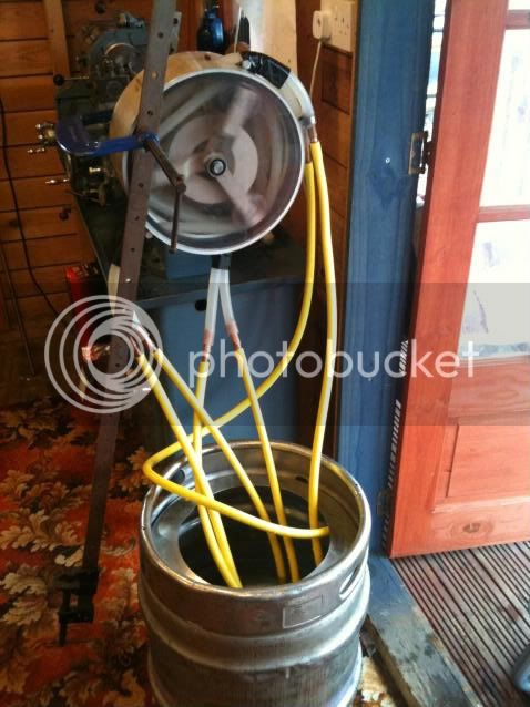
I have finally got around to the first test of the Mk2 pump, with it's three 1/2" silicone tubes. As set up in the photo, all three pump tubes prime ok from dry at about 20 RPM and at 66 rpm they combine to chuck out 2.66 imperial gallons per minute (so thats 3.2 USGPM or 12 litresPM) it still pumps right down to zero RPM, and stays primed, so that's a good sign! I'm sure if I upped the speed it would pump way more, but we will see later.

I now have to sort some manifolds to smoothly position the silicone pipes as they enter and exit the pump body and they will also clamp the pipe securely as the pipe definitely tries to creep into the pump, but surprisingly it goes the opposite way to the rotation of the wheel holder, so the tubes that are sucking get pushed out....weird.

For those new to this, the pump body is 12"dia 1/4" wall alloy tube, 51/2" long and the end plates are 10mm thick Perspex, turned to fit. The drive shaft is 15mm dia.

I am driving the pump with my lathe and the sash clamp coming up from the floor is clamped on to stop the whole lot turning! this will all be tidied up sometime soon.

The best bit is the brewery now has 3 pumps

Mk2Peristalticpumptests.jpg
 
That pump rocks! :rockin:

It's come a long way since the first post. I love seeing new and creative gadgets. Keep pushing the envelope.

When you get there. I'm curious about flow rate as RPM's increase. Say from 40 to 80?
 
The carpet was carefully selected/reclaimed from the stepdaughters dining room as it looked reasonably "Pub like"! I vaugely know someone who has his lathe in the kitchen!!! Needless to say, he is sans SWMBO.
 
Using a similar setup to the previous picture but with improved inlet and outlet manifolds, I did 50 litre transfer tests at 105 rpm and 66 rpm. This gave an output of 5.6 and 3.141 US gallons per minute and took 7 and 10.5 minutes respectively. (Full results below)

Note that in the video, only one of the three silicone tubes is fitted, so the rectangular holes seen in the pump body sides are the access holes for the missing tubes. Also, the max speed is 105 rpm. Virtualy all the noise is the lathe, so when I give the pump it's own electric drive motor, things won't be so bad!!!!


The plan is to use pump tubes 1 and 2 in unison for mashing in and doing RIMS circulation, during sparging I will be using pump 1 for hot liquor and pump 2 for wort, so I will be able to sparge without needing to keep checking the flow rates as the pumps flow rates are exactly the same as each other, and that will then save the as yet unused and therefore "sterile" pump 3 for transferring the cooled wort from the boiler to the fermenter.

It seems that the tube needs to be held tight so it forms a "triangle" around the rollers. Doing this holds it tracking true and stable. If you try to keep the tube against the outer rim, which is what I was doing at first, it just flaps from side to side and gets in a right state. I have lubricated the pump interior with silicone grease to help things along as well. I have no reason to need a higher flow rate than this and it is my intention to not go above 66 rpm.

I will now set it up and let it run for a few days to try and get a handle on how reliable the tube is. If it lasts a test of a few days duration I will rely on visual inspection before each brewing session and cross my fingers.

If I was doing this again I would make three individual pumps that can be slid onto the drive shaft as and when required, then the third pump which is there as an emergency backup for the most part, would get to see next to no use apart from cold wort transfer..

The figures are per minute flow rates for 1 tube, 2 tubes and 3 tubes.

Litres 7.14, 14.28, 21.42 at 105 rpm......4.76, 9.52, 14.28 at 66 rpm

Imperial gallons 1.5705, 3.141, 4.71 at 105 rpm......1.047, 2.094, 3.141 at 66 rpm

US Gallons 1.886, 3.772, 5.658 at 105 rpm.......1.257, 2.514, 3.771 at 66 rpm
 
Last edited by a moderator:
How essential is the metal drum? Could the hose simply be pulled in tension over the rollers and still work adequately? It seems that could simplify construction considerably.
 

Latest posts

Back
Top