I am getting on with the Mk 2 pump, but have been a bit tied up with other brewery related tasks...
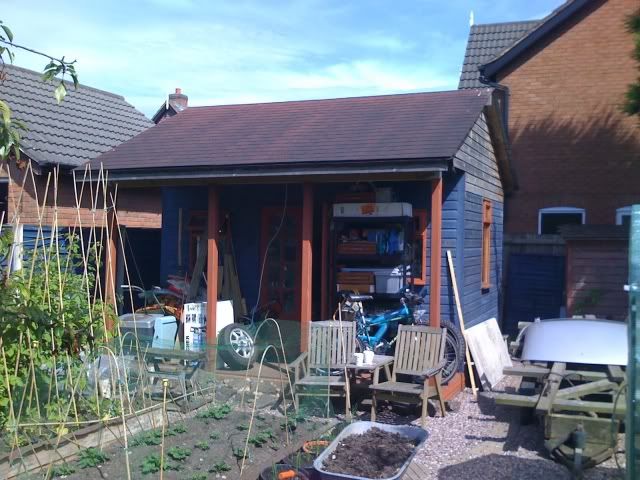
To get ready for the brewery build (Shed extension), I have chopped down two of next doors large trees, dismantled and re-assembled a small shed to elsewhere in the garden, dug up and re-positioned one of those bloody heavy 8' tall concrete fence posts and had a general tidy up. The extention will give me a 10' x 23' covered area, with a 16' x 5' covered corridor along the back. Got to go buy the wood soon.....
Anyway, back to pumps.
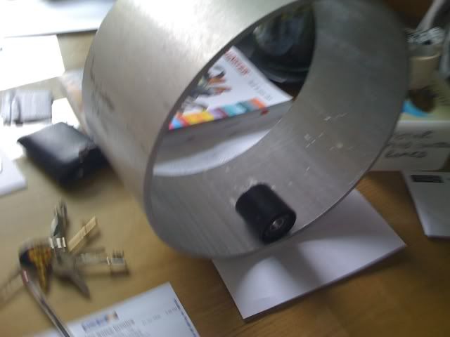
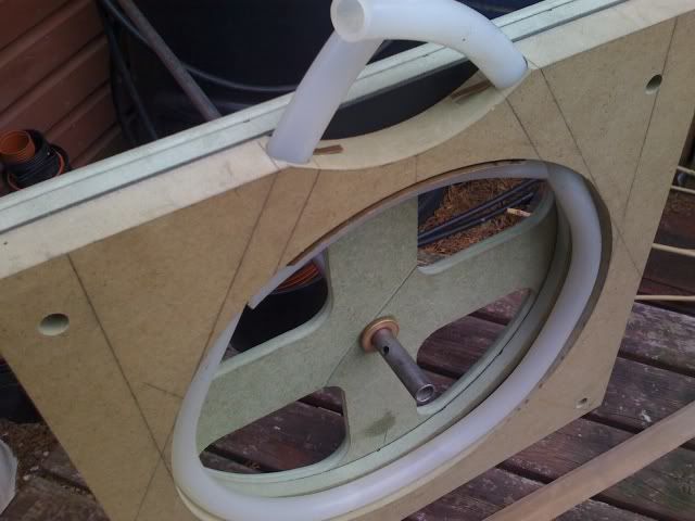
I have trimmed the ends of the alloy tube (12"od 11 3/4" id 5 1/2" long)
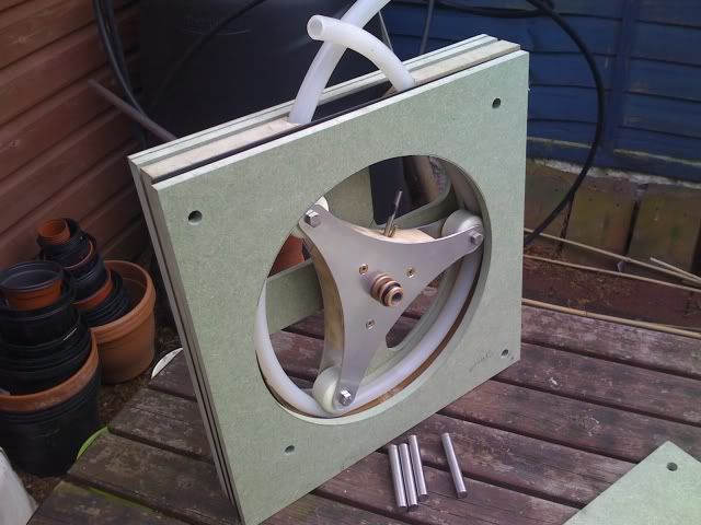
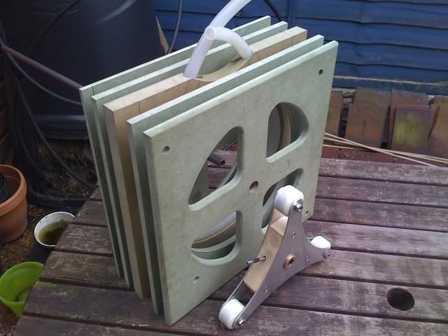
I have two bits of 10 mm thick 12" square Perspex that I have to turn a 11 3/4" diameter shoulder onto and bore holes for bearings. These will sit into the tube ends and provide concentric bearings for the shaft.
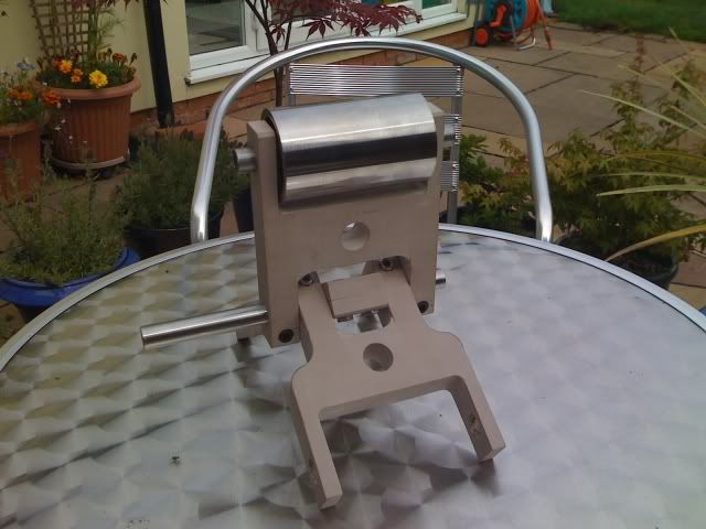
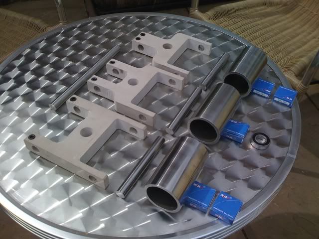
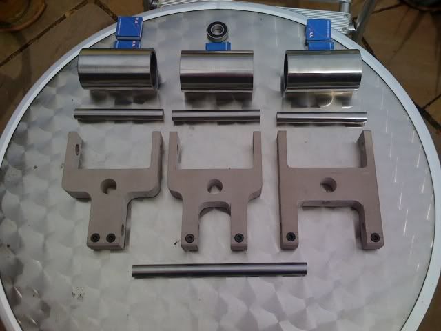
I have sorted out how to machine the three arms for the rollers, but cannot finalize the dimensions until I make the rollers.
I have got the steel tube for the rollers and am now searching for some round alloy stock to make the six end caps/bearing holders that will go in each end of each roller and hold concentric bearings for the rollers.
To machine the larger stuff I need to visit my mate who lives 100 miles away! but I will get to do that soon I hope.
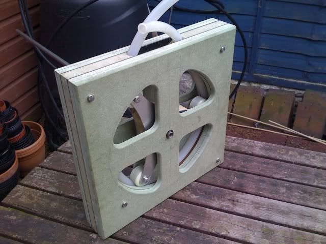
This pump will have three separate 1/2" silicone tubes, getting squeezed by rollers that are about 4" long and 2" diameter. This will give me the 2 pumps I need for sparging operations and an instantly available spare for emergencies. With all three tubes in use for high flow needs, I do not expect this pump to need to be turning at much over 50 to 75 RPM during use....


![Craft A Brew - Safale S-04 Dry Yeast - Fermentis - English Ale Dry Yeast - For English and American Ales and Hard Apple Ciders - Ingredients for Home Brewing - Beer Making Supplies - [1 Pack]](https://m.media-amazon.com/images/I/41fVGNh6JfL._SL500_.jpg)