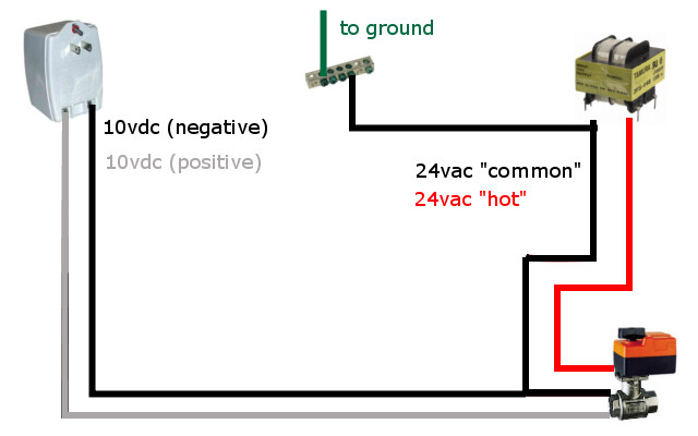
Ok, first, forget everything I said on my last post. I don't know why the hell I decided that the valve needed 12V. Your diagram is perfect. You need a DC volt meter.
Now, going to your question. Do this experiment:
Take the transformer, and power it up without connecting anything to the secondary.
Take a multimeter, and measure the voltage between any of the secondary leads and ground.
Now do the same between any of the secondary leads and neutral on the line voltage.
Now do the same, again between any of the secondary leads and the hot wire in the line voltage (be careful!)
You will see that, in all cases, the AC voltage will be "0", or very close to it (there can be some electrical noise in the wires).
That's because the secondary winding of the transformer is electrically isolated from the primary winding. The
only voltage you will find on the secondary is between the 2 leads. At this point, there is no hot wire in the secondary.
When you choose one of the leads (either one, doesn't matter) and physically connect it to the primary neutral wire, you're creating the hot wire, because the neutral wire is physically connected to ground, so, that other secondary lead that before had a 24V AC voltage towards the other lead only, now has the same voltage towards neutral (and ground), because your first lead IS ground.
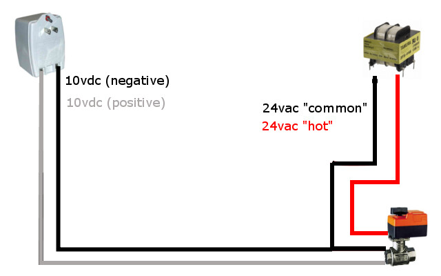
In this case though (the case of your wiring diagram), you're not really connecting the secondary neutral to the primary neutral. In a case like this, the secondary "neutral" is not really a neutral, but it is (as it is correctly named in the valve drawing) called a "common" wire, as it is the shared wire between 2 or more signals (in this case, the 24V AC and the 2-10V DC).
That means that,
theoretically, you won't find any voltage between any of the secondary leads and ground, unless there's an internal connection between the GND and neutral terminals in the PID (normally there isn't one).
So, to round it up a little:
* In a pure AC signal, there's no hot wire at all.
* You fabricate the hot wire, when you ground the wire that will be the neutral.
* If none of the wires are grounded (I think the right word is "bonded", but I'm not sure), there is no voltage between either one and ground. Again, that's theory. There's always some residual voltage, due to air conductivity, Foucault currents in the transformer, etc.
* The fact that you're attaching a DC signal to a wire carrying an AC signal doesn't affect anything, as long as the other wires don't touch. If they do touch, you will remember me.
* The neutral bus in your wiring diagram is not really a neutral bus, but a "common bus", as it's not connected to the grid's neutral, or ground.
* You don't need any resistor between terminal 3 and "common. Unless the instruction manual for the PID calls for it, don't use it.
* If the valve has an input impedance of 1 MΩ (for what you said) and you connect a 1 MΩ resistor between terminal 3 of the PID and the valve input, you're effectively cutting the voltage at the valve input in half. Don't do it.
* If, instead of connecting the resistor between 3 and the valve, you connect it between 3 and the common bus, you will be effectively
doubling the voltage on the valve. Again, don't do it.
In both cases, you will have a false reading on your volt meter.
I think that about sums it all up. Let me know if there's something else, or if you didn't understand something.


")


![Craft A Brew - Safale BE-256 Yeast - Fermentis - Belgian Ale Dry Yeast - For Belgian & Strong Ales - Ingredients for Home Brewing - Beer Making Supplies - [3 Pack]](https://m.media-amazon.com/images/I/51bcKEwQmWL._SL500_.jpg)