Help the InkBird ITC-100V

Homebrew Talk - Beer, Wine, Mead, & Cider Brewing Discussion Forum

Help Support Homebrew Talk - Beer, Wine, Mead, & Cider Brewing Discussion Forum:

This site may earn a commission from merchant affiliate links, including eBay, Amazon, and others.

mrtav

Member
Joined
Jan 30, 2013
Messages
5
Reaction score
2
Hello friends.
I've been putting together a panel based on theelectricbrewery.com
with the exception of the PID controllers.
I found a deal on the Inkbird ITC-100v which is a close match, but not quite the same as the Auber SYL-2352 used in theelectricbrewy.com's panel.
I've found in a previous thread that someone was experiencing the same dilemma pertaining to the NO and NC wiring connections.
The thread was answered and I learned that connections 11,12 = 13,1 on the SYL

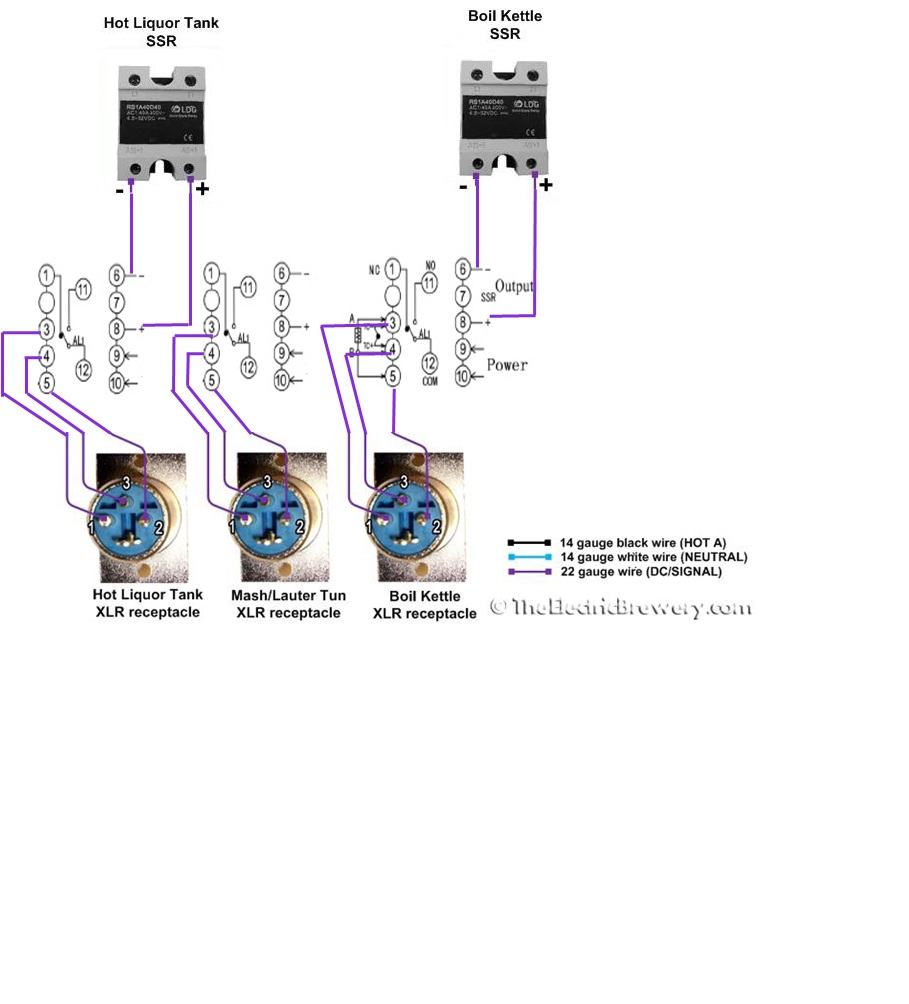
My question is: Going by the attached schematic (compliments of www.http://www.theelectricbrewery.com) how can I achieve the same (or similar) results using the ITC (diagram attached)

alarms.jpg


ITC-100v.jpg


Auber syl-2352.jpg
 
Last edited:
I'm assuming you read this thread and still have some questions. These PIDs are not that complicated once you understand what the different parts do. The Inkbird only has 1 alarm relay, not 2, so the jumper between 1 and 14 on the SYL diagram won't apply to your setup. I only have 1 alarm (per PID) on my control panel, I'm not quite sure how a 2nd would be used anyway.

Because I'm a teacher, I'm going to go a bit overboard on this so you can approach the next problem with some understanding of WHY to do it this way, not just following step-by-step directions. :)

You need power to the PID. Run your AC hot wire (from hot bus) to 9, and neutral return (to the neutral bus) to 10. Now you have power!

You need to also supply 110v power to the alarm relay, so that when the alarm temperature is reached and the alarm relay closes, power will flow through it to the alarm/switch. Jumper pin 9 (hot) to pin 11, then run another wire from pin 12 to the alarm switch (if using a switch, otherwise just straight to the alarm). The alarm itself will also need a neutral return to the neutral bus.

You use the NO (normally open) terminal so the alarm circuit will be open (or broken) during normal operation. When the alarm temperature setting is reached, a relay inside the PID will close the internal connection between 11 and 12, allowing power to flow from the hot bus through the relay (11 to 12) and out to the alarm. If you connected your hot line to pin 1 instead, the alarm would be alarming right away until you reached the set temperature, and then it would turn off.

That does it for the AC power. Now connect pins 6 and 8 to the corresponding DC input terminals on your SSR. Now the PID can control the SSR by supplying a control voltage to turn it on and off.

If you're using an RTD probe with 3 wires, connect the two like-colored wires to 4 and 5, and the third wire to pin 3. Now the PID has temperature information and you're all set.

If you look at Kal's diagram one piece at a time, you'll see a wire from the hot bus running to each PID's pin 13, giving them all power in parallel. What you don't see is that in another diagram, pin 9 (AC power on the SYL) is also connected to the hot bus. In my explanation above, I'm suggesting jumpers between pin 9 on your PID to pin 11, rather than a separate AC hot line for the alarm circuit. You could do it either way. Regardless, you're just supplying a hot wire to each pin, one for power and one for alarm.

Make sense?
 
Hello,
Yes, I did read that thread, much appreciated for that explanation.
Now I understand the connection on number 1. I couldn't place it's use going by Kal's schematic.
And, thanks for pointing out pin 13 to the hot bus.
I had already wired the pins 9 and 10 so, all I need to do from here you're saying is to just jumper from 9 to 11? That makes sense, plus I'll save a little wire.
I really appreciate the help.
Thanks.
 
I am using the Inkbird ITC-106VH PID and the Inkbird Digital IDT-E2RH Timer. I combined some diagrams and came up with these diagrams. Is there anybody that has used this combination? Or, can anyone validate these diagrams as correct?

Thanks!!!
Kevin

ACpower.JPG


Signals.JPG
 
I am using the Inkbird ITC-106VH PID and the Inkbird Digital IDT-E2RH Timer. I combined some diagrams and came up with these diagrams. Is there anybody that has used this combination? Or, can anyone validate these diagrams as correct?

Thanks!!!
Kevin

If this is correct, you sir are a godsend! I have been looking all over for these exact 2 diagrams (if they are in fact correct, which they do look like they are).

Can @doug293cz confirm this?
 
Yeah. It would be good if someone could check my work! Not an electrician.
 
As far as I can tell, the InkBird IDT-E2RH is just a rebadged Sestos B2E (in fact the front panel says "TIMER B2E".) InkBird doesn't list the IDT-E2RH on its product page. So assuming this is correct, then the wiring looks correct. The Sestos B2E manual sucks, so I can't really be sure about the timer wiring, but it appears reasonable from what I can decipher of the manual. The PnP input mode needs to be set for the reset button to work correctly (I think.)

Some comments:
  • The diagram shows both a (flashing) lighted buzzer and a separate lamp for the alarm. This is redundant. If the buzzer doesn't have a built in lamp, then having a separate alarm lamp makes sense.
  • All of the 120V wilring is shown as 14 AWG. All of the circuits will draw much less than 1A, so you could use 16 or 18 AWG wire to make wiring a little easier.
I going to assume you don't have any questions about the high current (element power) parts of the circuits.

Brew on :mug:
 
Sounds good. I will be powering my panel in the next week (+/-) so I will report any discrepancies.
 
As far as I can tell, the InkBird IDT-E2RH is just a rebadged Sestos B2E (in fact the front panel says "TIMER B2E".) InkBird doesn't list the IDT-E2RH on its product page. So assuming this is correct, then the wiring looks correct. The Sestos B2E manual sucks, so I can't really be sure about the timer wiring, but it appears reasonable from what I can decipher of the manual. The PnP input mode needs to be set for the reset button to work correctly (I think.)

Some comments:
  • The diagram shows both a (flashing) lighted buzzer and a separate lamp for the alarm. This is redundant. If the buzzer doesn't have a built in lamp, then having a separate alarm lamp makes sense.
  • All of the 120V wilring is shown as 14 AWG. All of the circuits will draw much less than 1A, so you could use 16 or 18 AWG wire to make wiring a little easier.
I going to assume you don't have any questions about the high current (element power) parts of the circuits.

Brew on :mug:

Thanks Doug!

Sounds good. I will be powering my panel in the next week (+/-) so I will report any discrepancies.

Please let us know. I should have the final few components in the next couple weeks. Would prefer to hold off on buying the ITC-106VH until you can confirm it all works. :mug:
 
Decided and pulled the trigger on the ITC-106VH ones with the inkbird timer. Just waiting on my SSR's, momentary switch, 3 way switch and key switch. Need to doorbell transformers but will probably swing by home Depot later. I think to avoid the hassles I will just pony up and buy the wiring kit on Kal's site. I can't be arsed to find everything myself. Worse enough I have to acquire hardware to screw everything down.

I will update when I get her all wired up!

View attachment 1497557249086.jpg
 
Decided and pulled the trigger on the ITC-106VH ones with the inkbird timer. Just waiting on my SSR's, momentary switch, 3 way switch and key switch. Need to doorbell transformers but will probably swing by home Depot later. I think to avoid the hassles I will just pony up and buy the wiring kit on Kal's site. I can't be arsed to find everything myself. Worse enough I have to acquire hardware to screw everything down.

I will update when I get her all wired up!

I got my doorbell transformers from HD also. I prefer to use multiple supply sources so the wife can't add it up easily.
 
The PnP input mode needs to be set for the reset button to work correctly (I think.)

I believe you would be correct as I plugged her in yesterday for the first time and the reset sw does not work.

Would you know how to change the PnP input mode?
 
I believe you would be correct as I plugged her in yesterday for the first time and the reset sw does not work.

Would you know how to change the PnP input mode?

All I can say is RTFM. I don't have any experience with this device, and only know what I read in the crappy manual. If you don't have the "manual" (it's only 4 pages), I can send you a copy - PM me.

Edit: Another thing you could try is moving the connection from terminal 4 on the B2E to terminal 5. This makes the input mode of the reset function NpN (I think), which might be the default, so it doesn't need to be set explicitly.

Brew on :mug:
 
Last edited:
All I can say is RTFM. I don't have any experience with this device, and only know what I read in the crappy manual. If you don't have the "manual" (it's only 4 pages), I can send you a copy - PM me.

Brew on :mug:

I totally would have if it came with it :D

I will search online for it, if my results come up empty, I will PM you. Thanks!
 
I totally would have if it came with it :D

I will search online for it, if my results come up empty, I will PM you. Thanks!

Just remembered, can't attach a .pdf file to a PM, so you'll need to include an e-mail address.

Brew on :mug:
 
I changed the wiring slightly because it is difficult to get 3 spade connectors under one connection point. I should be able to test this week.

Slide2.JPG


Slide1.JPG
 
I changed the wiring slightly because it is difficult to get 3 spade connectors under one connection point. I should be able to test this week.

I went ahead with the original diagram. It is tricky to get all 3 spade connectors on that pin.

I may just go ahead and change mine up to this as well.

By the way, I did power her up and your wiring is correct. Like mentioned by Doug, you just have to change the PnP setting on the alarm PID for the reset button to work.

Thanks again for sharing this.
 
So, I have brewed 5-6 batches with my electric brewery and the wiring is correct for Inkbird PIDs and timers. I did make the changes to my panel for the reset button. The diagrams below are updated:
 

Attachments

  • Slide1.jpg
    Slide1.jpg
    120.8 KB · Views: 520
  • Slide2.jpg
    Slide2.jpg
    108.8 KB · Views: 839
So I just powered up for the first time last night. Your diagrams helped tremendously.

I gotta go through the whole setup of the PID's still, but the temps are reading accurate.

My volts and amps meters are not working, gotta sort through all that and the alarm reset button is wired up in the earlier diagram, so I have to change that as well.

IMG_20171206_213608.jpg
 
So, I have brewed 5-6 batches with my electric brewery and the wiring is correct for Inkbird PIDs and timers. I did make the changes to my panel for the reset button. The diagrams below are updated:

Nice work! Does the alarm go offf when the set temp is reached on the PID? For some reason my 106vh wont do that... it’s annoying.
 
Maybe you could switch to self-tuning mode from the default mode of PID control? Here is the section from the manual.

Output_Settings.png
 
Nice work! Does the alarm go offf when the set temp is reached on the PID? For some reason my 106vh wont do that... it’s annoying.
Most PID's with alarms, have multiple alarm modes. To get the behavior you want you need to set the "High limit alarm" value to your set point, or set the "Positive deviation alarm" value to 0. The second option is probably better, as the alarm will then follow changes in your set point without having to reset the "High limit alarm" value.

Brew on :mug:
Ugh -- I searched high and low for this answer and this is the only place it seems to exist. Thank you for posting this. I thought something was wrong with my pid.
 
Hahaha my bad.. My first language is French.

On the schematic by kwilson16, the wiring show the alarm plugged into the timer on the NC(normally close). I think it should be plugged to NO..?
 
Hahaha my bad.. My first language is French.

On the schematic by kwilson16, the wiring show the alarm plugged into the timer on the NC(normally close). I think it should be plugged to NO..?
Normally, the alarm indicator would be connected to the NO contact of the timer alarm relay. This would change if the timer operated in a manner that closed the relay until the unit timed out, and then opened the relay. In this case the schematic would be correct.

Brew on :mug:
 
Back
Top