• Please visit and share your knowledge at our sister communities:
  • If you have not, please join our official Homebrewing Facebook Group!

    Homebrewing Facebook Group

Finally...Wooden Single Tier Underway

Homebrew Talk

Help Support Homebrew Talk:

This site may earn a commission from merchant affiliate links, including eBay, Amazon, and others.
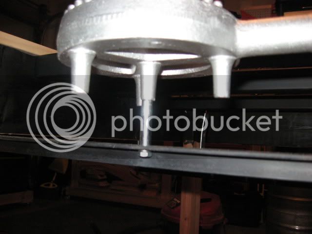
All I did was drill a hole into each end of the angle iron that the 5/16" all thread would fit through. The tighter the better while still allowing it to slide up and down the all thread since the weight of the burner will cause it to lean one way or the other. I then used a 5/16" nut on the underside of the angle iron. This makes it adjustable. To combat the lean caused by the weight of the burner, I just put a nut on the top side of the angle iron to sandwich it and hold it in place tightly.
 
I got the steel painted and the casters put on last night. One of my crossbeams was different than the others since I was just short on the original tubing. I bought the same size steel but it was zinc coated. The paint seemed to stick fine and looked good even right after I cured it in the grill but as soon as it cooled, the paint curled up and came off. Not all if the paint came off but did as soon as I wiped it with my hands. I'm going to try and sand it and then paint it again to see if I get a better result.
 
The only place for a bolt on the smaller burner is in the center post. I went to Lowe's and got a 65mm M6x1.00 bolt to replace the much shorter one that was in there. I used the longer bolt with a 1 inch and a 1/2 inch spacer with a lock nut. It's actually pretty snug.

IMG_1791.jpg
 
Nice build! What are the part numbers for the honeywell valves and the temp controllers? I have my stand built but I just need to get the rest of the components.
 
The valves are these (Honeywell VR8200's) and the temp controllers are these (Auber 2362). The temperature probes are on the same website and were these.

As for the burner mount, I added the spacers because I needed to get the burner up that extra inch and a half. You could mount it right to the steel if you didn't need the extra height.
 
Hopefully, today I'll be picking up the pieces for my propane manifold and control box. I was going to use the yellow teflon tape to piece my manifold together but some are kind of against it and would rather use the paste. I've done other smaller propane fittings with the tape and haven't really had any issues.

To hold true to my wooden theme, I'm going to build the box out of, you guessed it, wood! I'm considering routing and attaching the wiring to the bottom of the box and hinging the top so I can open it and access things easily. I'm not sure yet how I will attach it to the stand. I'm thinking of a piece of decorative iron for a mailbox that can be swung out of the way for storage.
 
Alllllriiiiight! I finally got the gas manifold all put together and the chiller mounted. I forgot to take pics of the chiller so I'll have to add it later.

So, I ended up using yellow teflon tape on all of my gas connections and haven't had any leaks. I went ahead and ran all three burners as low pressure which meant I only had to buy one regulator for the whole deal. As far as propane is concerned, all I have left is to mount the pilot lights and the thermocouples.

Here's the manifold with the valves:

IMG_1795.jpg


Where the manifold attaches to the hose that's attached to the tank. I had to use a 1/2" FIP to 3/8" FIP connected to a 3/8" MIP nipple to fit the hose.

IMG_1798.jpg


One of the valves. You can see that the pipe goes into the gas rated ball valve and then into another 2" pipe and then threads directly into the valve. On the output of the valve you can see the connector that came with the hose. It's a 1/2" MIP to 3/8" Flare fitting with a built in safety valve.

IMG_1796.jpg


This is the connector to the burner. I've seen quite a few people in other threads with questions on how to connect these to the burner. The fitting here is a 3/8" Flare to 1/4" FIP.

IMG_1801.jpg


I drilled the orifices for all three burners. On one of the bigger banjos, a 3/32" bit did the trick. On the other, I ended up going to a size 40 wire gauge bit to get a flame that was more blue than yellow. That one was a real B*. It would give me an ok flame but would pulse for some reason where the other orifice worked fine after drilling it once to 3/32".

IMG_1805.jpg
 
I just skimmed the thread, but I didn't see anyone mention charing or burning of the wood. Unless you put some shielding on the sides near the burners, you will eventually burn the wood.

I'm jealous of your stand though. I have a 3 tier wood stand now, but I want to build a single tier soon. I'm also thinking of going electric, so I may have to copy your design.
 
I painted the inside of the upper level with black high temp paint. I know this won't do much to keep the wood from charring but I've been on other threads for guys who built wood single tiers like this and they said they haven't had issues with it. Either way, I sandwiched some aluminum flashing between the 2x6 and that top layer of trim and then bent it down over the wood.
 
Could you give a little more detail on your weldless thermometers and ball valves? How did you install them? What parts did you use? Do they work well? How did you choose location? Etc.? I'm getting ready to finish my keggle and would really appreciate the insight!
 
I got the wedless fitting with the ball valves in kit form from BargainFittings.com and my weldless sightglasses with thermometers I got from BrewHardware.com . They're prices are great, the shipping was quick and saved me the hassle of having to piece them together. Normally, I'll do something the hard way if it will save me a couple bucks but this really was worth it.
 
I got the wedless fitting with the ball valves in kit form from BargainFittings.com and my weldless sightglasses with thermometers I got from BrewHardware.com . They're prices are great, the shipping was quick and saved me the hassle of having to piece them together. Normally, I'll do something the hard way if it will save me a couple bucks but this really was worth it.

Awesome! Thanks, man.
 
The control box has been underway for a little while now...actually, a couple of them. I've made more than one with different wood and this is the first one that I like. Go figure it would be made out of the most costly wood. The box is made from a nice piece of solid poplar. I chose it because it's closer in color to the pine used for the stand but it generally milled a lot straighter than even the more high quality pine at Lowes and, it's a bit cheaper than oak.

The top is the same poplar that I cut into strips, mitered and dado cut to inset the plexi-glass for mounting my switches and temp controllers. The bottom panel is on my work bench and will have the other electrical components attached to it.

Two Controllers, Off-Auto-On switches for the controllers, pump power switches and main power switch.

IMG_1817.jpg


IMG_1819.jpg
 
Definitely. I plan on having everything in one bundle coming up to the lid and then branching off. Careful use of zip ties and properly cut wire lengths should do the trick....in theory.
 
Nice project. How long have you been working on it?

I like your control box in particular. Looking forward to seeing the finished product and learning how it works.
 
I ordered to parts over the course of a six month deployment and have been putting it together since mid-December. Take into account that I've had to go back to work and now have a 6 week old infant. All I have left is this control box and a test run and I'll be ready to brew.
 
I've been spending this week wiring up the control box and now I've hit a wall. I've got 120Vac going everywhere it needs to go, even up to the transformer. The transformer is a standard doorbell chime transformer from Lowe's with posts for 8V 10A, 16V 10A and combining the two making it 24V 20A. No matter which way I wire it up, my multimeter is reading .2Vac on the other side of the transformer. My multimeter only has settings for 600V and 200V on the AC side but being digital, it should read down to 24Vac with no problem.

Here are some pics of my wiring.

Main Power
IMG_1828-1.jpg


Pump Power
IMG_1825-1.jpg


Internal wiring:

IMG_1824-1.jpg


Close up of Transformer wiring:

IMG_1821.jpg


PID and Switch wiring (took this at an angel because of the glare off of the plexi-glass):

IMG_1823.jpg
 
So I returned the transformer and got a new one...still no voltage on the out side. What am I doing wrong here? When I hooked up the new one, it got hot but not too hot and I still had no voltage.
 
This door chime xformer ...these multiple output voltages it can produce would make me highly suspect.
I would set your multimeter to VAC and measure the 2 output lugs with everything disconnected.
If you are not getting 24 vac, then the output of the xformer needs to be modified, jumpered, or better yet, just get a no frills 120vac to 24 vac xformer from radio crap, pexsupply, or amazon.
If you are getting 24vac then you have a short in your barrier strip or somewhere downstream.
good luck.
 
Alright, it turns out...I'm not crazy. I bought the Radio Shack transformer and it burned up and I can't figure out why so, I bought another transformer from Ace Hardware. It was the same door chime transformer as the others and I was skeptical. I got home, hooked it up and it hummed away AND is reading 24-28V on the secondary side. It is wired up the same exact way as the other three were. I felt like I was taking crazy pills. How bad can your luck be to by three bad transformers from two different stores?? I was about to lose it!

EDIT: Well, I may have mis-spoke. I'm reading 24V right off of the transformer but when I wire the 8V and the 16V pole together on the 24V terminal strip, it reads zero. Why is it reading zero when I combine them? on the same strip?
 
From the picture of your barrier strip, I notice you have some jumpered and some are isolated. Looks like you are shorting out your ac and causing some kind of out of phase loop.
Without burning out another xformer, I would trace continuity through each barrier strip contact to see what and how everything is connected.
I would get non jumpered barrier strips and just do the jumpers myself with some wire.
 
Another tip:
Where is your 24 vac neutral?
From your picture it seems that the 8vac and 16vac get combined to make 24 vac but I 'm curious to see if you need to tap off the middle lug off your xformer
How are you measuring 24vac?
 
I finally got the electrical issue figured out thanks to the guys who chimed in the this thread I started. It was a terribly simple fix that I just couldn't see for some reason. Here is the final result of the fix:

IMG_1838-1.jpg


The PID's and Switches:

IMG_1840-1.jpg


All that's left is to mount the control box to my stand on a swing arm and stain everything. I've gotten so impatient that I'll probably brew before I get that part done!

Here are the valves all wired up:

IMG_1836.jpg


GFCI and DC connectors to valves:

IMG_1834.jpg


RTD Temp Sensor connectors:

IMG_1832.jpg
 
Back
Top