Natdavis777
Well-Known Member
I know this is probably a dead horse topic, but I would appreciate any feedback on this diagram to see if I am in the right direction.
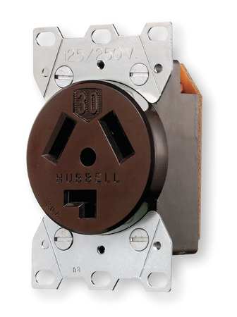
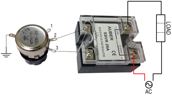
I plan on purchasing a BoilCoil in the near future, and wanted to make a simple controller for it instead having to but one. I use a keggle system, so I will be going for a 15gal 240v coil. I just put in a 30a 220v outlet in the garage solely for brewing. I want to pick up a box, 30a SSR, potentiometer, and 30a switch for the box. I thought about going with a PID, but for simplicity sake, I want to just stick with a potentiometer.
Below is the wiring diagram. I just want to confirm if this is correct. The power will be supplied via the wall, and a female cord will exit the box to connect with the element.


![Craft A Brew - Safale S-04 Dry Yeast - Fermentis - English Ale Dry Yeast - For English and American Ales and Hard Apple Ciders - Ingredients for Home Brewing - Beer Making Supplies - [1 Pack]](https://m.media-amazon.com/images/I/41fVGNh6JfL._SL500_.jpg)