Feedback On Controller Wiring

Homebrew Talk - Beer, Wine, Mead, & Cider Brewing Discussion Forum

Help Support Homebrew Talk - Beer, Wine, Mead, & Cider Brewing Discussion Forum:

This site may earn a commission from merchant affiliate links, including eBay, Amazon, and others.

Natdavis777

Well-Known Member
Joined
Apr 29, 2012
Messages
2,871
Reaction score
567
Location
Brownsburg
I know this is probably a dead horse topic, but I would appreciate any feedback on this diagram to see if I am in the right direction.

I plan on purchasing a BoilCoil in the near future, and wanted to make a simple controller for it instead having to but one. I use a keggle system, so I will be going for a 15gal 240v coil. I just put in a 30a 220v outlet in the garage solely for brewing. I want to pick up a box, 30a SSR, potentiometer, and 30a switch for the box. I thought about going with a PID, but for simplicity sake, I want to just stick with a potentiometer.

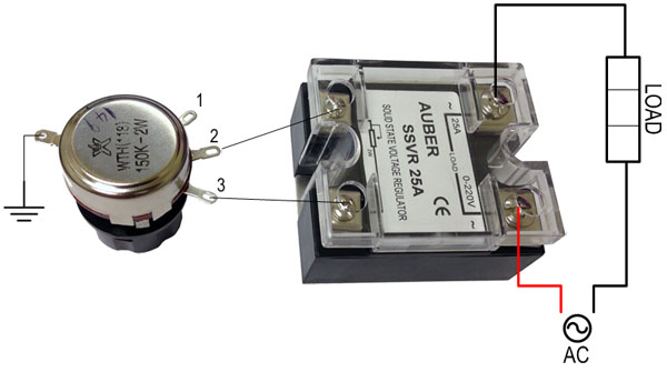
Below is the wiring diagram. I just want to confirm if this is correct. The power will be supplied via the wall, and a female cord will exit the box to connect with the element.

Screen Shot 2015-04-01 at 2.18.30 PM.png
 
Is that an SSVR? If it's an SSVR, then its correct, except for the potentiometer wiring. Never seen an SSVR with three terminals. If it's 240V you will have one side of the element hot as soon as you plug it in - be careful.

And the correct wire colors for household 240V in the U.S. are usually Black = Hot, Black = Hot, White = Neutral, Green = Gnd.

SSVR25A.jpg
 
SSVR correct. I did this in Word really quick so I used red as hot and black as neutral.

How should the potentiometer be wired correctly?

I have the grounds going to the SSVR where it connects to the heat sink, so it's common ground, not a terminal. Should I not do that, and run incoming ground to outgoing ground instead?

Also, with the switch inline with incoming power and the SSVR, it shouldn't be hop if the switch is open, correct?

See the picture I posted with the potentiometer? You can wire it that way, or wire it that way and jumper pins 1 & 2 together - Either way. Your picture is mostly right but the third wire threw me off - it must be the ground.

You can ground everything on the heat sink, that should work fine. the circuit on my boil kettle is nearly identical and I've got everything grounded on the enclosure including the heat sink, but if you want to put it on the heat sink, go ahead.

On 240V household systems in the United States, both black wires are hot - so if you only switch one of them the other will still be hot (Think of it as each leg is 120V and when you add them together its 240V). The way I deal with this on my panel is both hot legs of the 240V go through a DPDT relay so that I can turn it off. You could use a DPDT switch that is rated for the current and voltage you system will use.

I'm at work right now so I cant really draw you a diagram - but I can tomorrow possibly.
 
Gotcha. I appreciate the help.

I guess my confusion comes in that I was going to run 3-wire 240v, since it looks like the plug for the Boil Coil on has 3 terminals on it.

The wire I have ran in my garage is 10-2, so ground is obviously the bare copper, then I get 120V from the (Black) and 120V from the (White), correct?

So getting a dryer cord to match the 3-prong outlet with stripped ends, going into my control box, I would need to wire the (White) and (Black) to a DPDT switch (which I do not know how to do) to completely kill power unless the switch was closed. Is this correct?

If not, do I need to run different wire from my box to the outlet, and install a certain type of outlet? And if so, how will the 3-prong BoilCoil plug in?

Sorry for all the Qs

Edit: I see where I would still have 120v hot to the element with the single switch "open". For simplicity sake again, leaving the switch in line with the main power to the SSVR, and adding another switch in line with the other "hot" wire going directly to the element, this should kill all power to the element correct? And in order to get 240v, both switches would have to be closed. I know the DPDT switch probably negates the use of two switches, I just want to see if my logic is correct.
 
Note that a DPST switch capable of switching 25amps/240v is pretty expensive. Most people buy a contactor and a switch for @ $20 and use that to switch main power.
 
Gotcha. I appreciate the help.

I guess my confusion comes in that I was going to run 3-wire 240v, since it looks like the plug for the Boil Coil on has 3 terminals on it.

The wire I have ran in my garage is 10-2, so ground is obviously the bare copper, then I get 120V from the (Black) and 120V from the (White), correct?

So getting a dryer cord to match the 3-prong outlet with stripped ends, going into my control box, I would need to wire the (White) and (Black) to a DPDT switch (which I do not know how to do) to completely kill power unless the switch was closed. Is this correct?

If not, do I need to run different wire from my box to the outlet, and install a certain type of outlet? And if so, how will the 3-prong BoilCoil plug in?

Sorry for all the Qs

Edit: I see where I would still have 120v hot to the element with the single switch "open". For simplicity sake again, leaving the switch in line with the main power to the SSVR, and adding another switch in line with the other "hot" wire going directly to the element, this should kill all power to the element correct? And in order to get 240v, both switches would have to be closed. I know the DPDT switch probably negates the use of two switches, I just want to see if my logic is correct.

3 wire 240V is two black power wires and ground. You have enough wires for your boil coil.

The only time you would use the white neutral wire is when you need to split 120V out. If you take a meter and measure the voltage, you will have 240V ac between the two power wires (If it's 10-2 Romex it should be the two insulated wires - one black, one white - confusing...). If you have the third neutral wire, measuring between hot and neutral will give you 120V. The bare ground is just ground.

A three wire outlet is two hot wires and ground - no neutral wire - so it should be good for your boil coil. is it a 30a 3 wire outlet like this?

5Z841_AS01.JPG


RV-Dryer_Outlets.jpg
 
Its 10 2 Romex that I ran. Inside its insulted black, insulated white, and bare copper for ground. The outlet I am installing is a L6 30 style, which seems to be the standard for the boilcoil power wire.
 
Back
Top