• Please visit and share your knowledge at our sister communities:
  • If you have not, please join our official Homebrewing Facebook Group!

    Homebrewing Facebook Group

Electric Rig Wiring help needed.. any E.E.'s out there?

Homebrew Talk

Help Support Homebrew Talk:

This site may earn a commission from merchant affiliate links, including eBay, Amazon, and others.
kevin9167, so basically the receptacle is a mechanical switch, which then negates the need for the SSR? And yes, it would make sense that for pumps, heaters, etc. that a mechanical switch should suffice due to longer duty cycles.

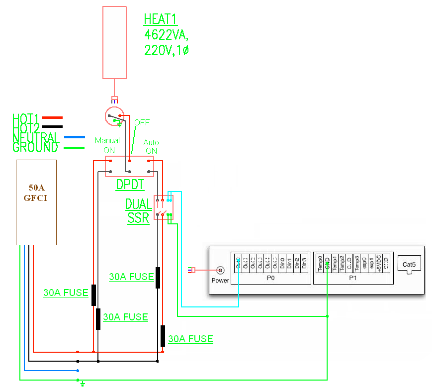
As for the 40a SSR on the elements, what I was proposing was to exchange my 25a SSR's since I will be using a mechanical relay instead (the receptacles). I would exchange the 25a SSR's for three 40a SSR's. Then run two 40a SSR's for each element... in essence a "dual" ssr.

Savvy?
 
One question I have is, how are you heating your mash?
Is that element going in the grain, or is it a RIMs setup?

Either way that seems like a big element. Our rig uses a 5500w 240v for the HLT, a 5500w 240v for the boil, and a 1200w 120v for the rims.
These are on a 50amp circuit, as we never have the HLT and the Boil on at the same time.
 
kevin9167, so basically the receptacle is a mechanical switch, which then negates the need for the SSR? And yes, it would make sense that for pumps, heaters, etc. that a mechanical switch should suffice due to longer duty cycles.

Savvy?

You DO need SSRs for the 120v receptacles. The BCS is outputting 5vdc it will not turn on the 120v receptacles.
 
One question I have is, how are you heating your mash?
Is that element going in the grain, or is it a RIMs setup?

Either way that seems like a big element. Our rig uses a 5500w 240v for the HLT, a 5500w 240v for the boil, and a 1200w 120v for the rims.
These are on a 50amp circuit, as we never have the HLT and the Boil on at the same time.


I was wondering when someone was going to ask that!

The element will act as a "direct fire" element. The inspiration comes from here: http://www.speidel-getraenkebehaelter.de/braumeister.htm

After doing extensive research on the braumeister and RIMS type systems, and after weighing all of the information out there, I felt comfortable going this route with my setup. I was not going to reveal too much until I had it fully implemented and tested, but alas, someone "caught" me!

I have taken into account any issues that might arise with this setup, I think! I concede I may run into some issues at first, but with the physical setup of the MLT as well as the power/capabilities of the BCS I believe that ultimately I will be able to dial-in the "direct fired heater element MLT" to work just as I want/need it.

:mug:
 
This is my plan. I have built the e-keggles (I've been switching them manually!).

I have bought the SSRs ($28), but haven't pulled the trigger on the PID. Maybe tonight. I want to use just one PID since I can't run more than one element at a time anyway (current limited).
Heater_Control.jpg
 
Passedpawn, thank you for that! I look forward to being able to pore over it a bit more in depth tonight when I have the time to really focus on it!

It is hard to read the SSR model#, do you happen to have the crydom SSR model number on those?
 
It is hard to read the SSR model#, do you happen to have the crydom SSR model number on those?

D2425D. Dual 25A (total of 50A continuous if heatsinked well; see the derating curves in datasheet). Like I said, they are available on Ebay for $28.

D2440D (I think) for 40A model. The last "D" indicates dual.

FYI, first SSR switches/pulses both legs of the AC at the same time, per the PID's output. Second SSR selects the heater and associated thermistor. Might fail miserably, but I'll be giving it a shot within the next week.
 
if the elements are cord n' plug connected, why not use the DPST SSR the right way, Connect it to a single receptacle and just plug in the Element you want to use?
 
Howdy,
I've made numerous assumptions with this, but here is a rough wiring diagram. I'll let the other posters peer review and point out errors:
http://img511.imageshack.us/img511/705/brewrig.png

Wow great first post Brewineer! Thanks so much... I have to head back to work in a few minutes, but look forward to studying this more in depth tonight!

I do appreciate you taking the time to do this!

:mug:
 
So, i studied the diagram that Brewineer submitted, and I broke it down to a single element drawing so I could see if I am understanding everything.

Additionally, I swapped out the two single ssr's for a dual ssr; I also added inline fuses where I think they should be installed.

Can you guys look this over and let me know if I am on the right track?

Thanks again guys!

4055318309_6bcae1e24a_o.png


http://farm3.static.flickr.com/2510/4055318309_6bcae1e24a_o.png


:mug:
 
you dont need 4 fusses, fuse each leg (2 total) then branch off the load side of the fuses to the SSR and the switch.
 
................--------------------
--{fuse}--[.............................]--(HOA switch)-----Heater
................-----(SSR)----------


So hard to draw with text.
 
Ok, so fuse each hot leg from the distribution block, and then after the fuse, branch again and send one branch to the SSR and the other to the DPDT?
 
yeah, you have the right idea with the fuses.

Good call with fuses, lazybean, we really don't want this to burn down.

Keep in mind you shouldn't run a ground wire from the BCS-460 to your ground distribution block, as the bsc-460 'ground' is actually the neutral. You don't want to inadvertently bond you ground and neutral lines with your BCS-460.
 
Keep in mind you shouldn't run a ground wire from the BCS-460 to your ground distribution block, as the bsc-460 'ground' is actually the neutral. You don't want to inadvertently bond you ground and neutral lines with your BCS-460.

BCS should really call that a "COMMON"
 
Keep in mind you shouldn't run a ground wire from the BCS-460 to your ground distribution block, as the bsc-460 'ground' is actually the neutral. You don't want to inadvertently bond you ground and neutral lines with your BCS-460.


Thanks for mentioning that!
 
I have talked about this before, Switching one leg of 240v leaves the entire circuit energized the entire time(even if the circuit is open, it is still energized). This is a huge Code violation, NEC and UL.
Also, because you are using multiple receptacles, elements and current ratings, you are going to have to use fusses to protect all the different ratings.

I just had a friend look up the UL code for heaters, and unless they have integrated Thermal protection they will each need their own set of fuses.

I'm sure there will be the usual flurry of Anti-code replies. but it still doesn't change the fact its wrong and unsafe.


Yes, the entire circuit is energized if you only kill one leg, but there isn't anything inherently unsafe about that.
 
Keep in mind you shouldn't run a ground wire from the BCS-460 to your ground distribution block, as the bsc-460 'ground' is actually the neutral. You don't want to inadvertently bond you ground and neutral lines with your BCS-460.

Not bad advice, but not necessarily for that reason. The BCS GND pin is a DC GND. If you connect the DC GND to earth ground, you're just forcing it to be a common reference point.

The BCS GND is not connected to the 'neutral' line. The 2 prongs of the 'wall wart' that power the BCS are attached to the primary coil of a transformer, and the secondary coil is fed through a rectifier/regulator to create DC voltage. This is all inside the 'wall wart'. In fact, transformers are used in this way to isolate AC circuits.

So should the BCS GND pin be connected to earth ground? Doesn't really matter. Personally, I don't because it doesn't need to be, and it may slightly increase the risk of noise into the DC circuits. Although I've never witnessed it causing ill effects.
 
The only reason you may want to bond the BCS to earth ground is to ground the chassis if it is made of metal, especially if you have 110v feeding into the thing on some dry contacts. From what I've glanced over it seems to be low DC voltage which isn't anything to really worry about.

What bothers me is this DPDT switch I keep seeing. For a 50 amp service you are looking at contactors, not relays or switches. Auber sells em cheap but they are only rated up to 40 amps. Thats what I used for mine and I dropped my service through 30Amp breakers for each element. Contactors usually only come with normally open contacts for the high current stuff. So it may take two contactors and a three position maintained panel switch to drive the DPDT-ish functionality.

Why bother with the fuses? Breakers are meant to protect wire from burning up, fuses are meant to protect devices. Being a big resistor there really isnt much to protect on an element. If it leaks to ground you breaker is going to pop, which should be rated less than the current rating of the wire. Either one isnt going to save your butt should you get hooked up to it. You'll be long dead before that fuse pops, should you become the dead short.

Ground the crap out of the chassis and everything metal in the system. Use the right size breakers and wire, GFCI is good extra protection.

U/L isn't really a mandated requirement to build anything to, unless you plan to sell these things and want to be able to insure yourself against any damages this thing may cause.
 
Not bad advice, but not necessarily for that reason.
The BCS GND is not connected to the 'neutral' line. The 2 prongs of the 'wall wart' that power the BCS are attached to the primary coil of a transformer, and the secondary coil is fed through a rectifier/regulator to create DC voltage. This is all inside the 'wall wart'. In fact, transformers are used in this way to isolate AC circuits.

You are correct; I'm not sure what I was thinking and feel pretty dumb now. Maybe I'm just stressed out/weary from work and can't think as well on my off time. It suffices to say that this project is much more interesting than anything I do at work.

What are the ratings of the DPDT switch being used?
 
Be careful on picking a switch, contactor or relay as inductive load ratings are different than resitive loads when switching or controlling your brewing system. By this the size of the contacts and their maximum rating like SSR's or SSRD's if your thinking properly the 75% maximum rule allows for a longer electronic component equipment life.
 
Back
Top