Electric conversion

Homebrew Talk - Beer, Wine, Mead, & Cider Brewing Discussion Forum

Help Support Homebrew Talk - Beer, Wine, Mead, & Cider Brewing Discussion Forum:

This site may earn a commission from merchant affiliate links, including eBay, Amazon, and others.
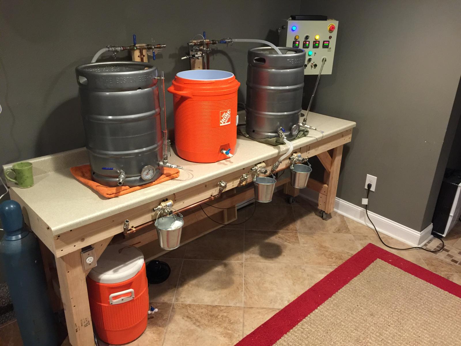
An all electric setup was my project last spring. About 5 batches through it and couldn't be happier. There is a few things I'd change if I did it over but what a fun project. REALLY improved consistency from batch to batch! Now I just sit back and watch it go while drinking a HB. :D

Good luck with it and enjoy the process.

Feel free to laugh at my sight tube on the HLT, drilled the hole a little low.

image.jpg
 
I know I am chiming in late here but went I brew i start out with almost 18 gallons of wort at the start of the boil and I use a 4500W element to heat it to boil. One thing to remember is that wile you are spaging into your boil kettle once your element is covered I turn it on and start heating to boil while the sparge is going one. A bit under powered here may not matter as much, by the time my sparge is complete my boil kettle is usually around 205 degrees F, not much further for a boil.


That was my game plan. Thanks for joint in.
 
Last edited by a moderator:
Great! Sometimes I get carried away. I get so used how some of our ground support shipment is built. I just end up thinking it should be the same on the brewery. I doubt I'll abuse my brewery as much as the power carts or hydraulic mules I have at work though. [emoji482]
 
Just curious what you don't like about the gap? (I'm assuming you're referring to my design... ;) ).


Kal


Since I've got the foam type of weather seal it looked like it had a gap in two sides (not really sealing the box), so I added a filler plate between the two brackets in the box and the outer cover plate so that the foam weather seal is fully supported. I've gained a lot of knowledge from your design. I'm tweaking it here and there for my own crazy ideas. By the way, the element cover issue I'm having with your design may just be me being anal.
 
Feel free to laugh at my sight tube on the HLT, drilled the hole a little low.

Mine was supposed to have polycarbonate tube in compression fittings when it was originally build years ago. The welder screwed them up, and had mine pointed into the keg, so I had to use silicone tube on barbs.
 
So I may have an issue. I just realized the heat sink I bought from Amazon is only rated to 26 amps. https://www.amazon.com/gp/product/B00899BEGI/?tag=skimlinks_replacement-20
Keep in mind that heat sinks don't really have a 'current' rating. What you're reading is simply the manufacturer trying to give you a rough idea on how it can be used. They probably assume better than average cooling conditions too.

The better the cooling the easier it is in the SSRs and the longer they will last. I believe you're using a 5500W and 3500W element and running both at the same time so up to 37.5 amps max draw.

How hot does it get after running both for 30-60 mins or so?

Kal
 
Last edited by a moderator:
How hot does it get after running both for 30-60 mins or so?


Kal


I'm still in the punching holes in the enclosure stage. I figured I'd stop in case I needed to get a different heat sink.
 
I finished piloting the holes for the ten XLR jacks that will be used for different float switches and temp probes in the system. I'll use a CNC engraver to label each Jack location. I felt like it was easier to make one big legend plate than ten individual legend plates, AND get them all to be uniform.View attachment ImageUploadedByHome Brew1473315034.238600.jpg
 
I liked the idea of a safe start interlock relay as recommended by the electric brewery. I'm using a standard DPDT relay. I added a line of relay pin 1 to the alarm so that if my switches aren't in the right position (all off) when I depress the momentary start button I'll get an alarm tone while the button is held.View attachment ImageUploadedByHome Brew1474494230.917012.jpg
 
It looks like the alarm will ring without doing anything the way it's drawn. When you release the momentary start button, what holds the connection to the main contactor? I think you need a latching circuit here. It is also not standard practice to switch a neutral in control wiring.
 
That relay circuit is so wrong! It would take several paragraphs to explain what is wrong and how to fix it. When "Start" is pressed, the voltage at pins 6 & 8 goes to zero, since the relay coil will drop the full 120V across it. Then there is no voltage going to the main power bus. And as pointed out there is no latching function. I suggest you go back to the Electric Brewery site and study the safe start circuit until you understand it.

Brew on :mug:
 
All relay coils for the interlock relay and the main relay are 110 AC. That's why I've got the neutral bus in there. Power comes in on relay pin 7, out 8, across the start button when it is pressed, and through all the switches to the neutral bus. This energizes the interlock relay switching the poles from throws 1 and 2 to 3 and 4. Now your interlock relay is latched from pin 8-6-4 through the main power contractor coil back to the neutral bus.
 
That relay circuit is so wrong! It would take several paragraphs to explain what is wrong and how to fix it. When "Start" is pressed, the voltage at pins 6 & 8 goes to zero, since the relay coil will drop the full 120V across it. Then there is no voltage going to the main power bus. And as pointed out there is no latching function. I suggest you go back to the Electric Brewery site and study the safe start circuit until you understand it.


Brew on :mug:


I have gone over the schematic in the electric brewer. He runs power through both poles to the DPDT relay and ties the two NO contacts together. He keeps the interlock relay energized through a maintained key selector switch, so there is no need for a latching circuit. I am using a momentary button, so I need the latching circuitry.
I will admit that my AC knowledge is not the best. I'm used to D.C. Since it's what I work with every day on aircraft. I know that the way the diagram I drew would work with a D.C. relay, but are you saying that I can not latch an A.C. coil relay?
Here is what I got from the electric brewer.View attachment ImageUploadedByHome Brew1474534805.580679.jpg
And the info on his relay he use http://doc.chipfind.ru/pdf/omron/mk2pns.pdf gives the relay this pinout.View attachment ImageUploadedByHome Brew1474534909.271390.jpg
So the schematic would look like this for him, but I'm still not seeing a latching circuit wired up to the relay coil. And again, he is using a maintained switch not a momentary button.View attachment ImageUploadedByHome Brew1474535012.322827.jpg
 
The problem with the way you have designed your circuit, is that when the start switch is closed, the interlock relay coil and the main power contactor coil are in series between 120V and neutral. Inductors (coils) in AC circuits act kind of like resistors in DC circuits, as far as voltage drop is concerned. So, assuming the two relays have similar inductances, the two coils in series will act as a voltage divider with about 60V across the interlock relay coil and 60V across the main power contactor coil. Neither relay will operate reliably, if at all, at half the rated coil voltage (and 1/4 the rated coil power.)

There is a similar problem with the alarm part of the circuit. The relay coil and alarm are in series, and operation is not assured.

This circuit can be redesigned to do what you want, but I won't have time to advise you until next week.

Brew on :mug:
 
Thanks that's a big help! I appreciate the AC lesson. Looks like I'd need a three pole relay for an alarm circuit. I guess the alarm is a little over kill anyway.
 
I think Kal's circuit design is more complex than required. I think you only need one pole of the relay for a safe start interlock, so you alarm function can be done with a two pole relay. I should be able to draw something up Monday.

Brew on :mug:
 
I think Kal's circuit design is more complex than required. I think you only need one pole of the relay for a safe start interlock, so you alarm function can be done with a two pole relay. I should be able to draw something up Monday.


Brew on :mug:


I agree. The second pole is needed if you're trying to use a momentary button.
 
One of the reason I used a DPDT (octal) relay in the design is because relays are the most common. You don't save any money by going to a "simpler" relay since 99% of the relay parts are required in all types and simpler SPST or SPDT are just just not as common because a DPDT can always be used in its place without all of the poles or throws connected.

This is why engineers like myself who designed plant floor circuitry always standardize on parts - an electrician can pull out the defective relay and put a new one in without checking what type it is when 3 or 4 types may be available (DPST/DPDT/SPST/SPDT). When it's always the same part there is less confusion and there is no need to stock multiple relay types. For this reason too, octal (DPDT) are considerably easier to purchase because they're in high demand. They may even be cheaper because of the higher volumes produced than "simpler" relays.

Good luck!

Kal
 
Here's an easier to understand (I hope) design for a safe start circuit. The relay pin numbers will depend on what kind of relay you use. Let me know if you have any questions.

Safe Start Circuit Example.jpg

Brew on :mug:
 
I agree. The second pole is needed if you're trying to use a momentary button.

No, you don't need a second pole to use a momentary contact "Start" switch. You just have to move the start switch to the other side of the hot branch, along with the NC interlock switches in the diagram above. It then gets bypassed when the relay latches, just like the interlock switches.

Brew on :mug:
 
No, you don't need a second pole to use a momentary contact "Start" switch. You just have to move the start switch to the other side of the hot branch, along with the NC interlock switches in the diagram above. It then gets bypassed when the relay latches, just like the interlock switches.


Brew on :mug:


Got it. Thanks for the fancy drawing. What did you use?
 
Got it. Thanks for the fancy drawing. What did you use?

I use an old (and unavailable) program called QuickCAD. It was eventually bought by Autodesk and killed because it was too good as low cost competition to other Autocad offerings.

Brew on :mug:
 
I use an old (and unavailable) program called QuickCAD. It was eventually bought by Autodesk and killed because it was too good as low cost competition to other Autocad offerings.


Brew on :mug:


Bummer. I need to google a free/cheap program to work on my whole wiring diagram this weekend.
 
Here's an easier to understand (I hope) design for a safe start circuit. The relay pin numbers will depend on what kind of relay you use. Let me know if you have any questions.

View attachment 371601

Brew on :mug:

Is the EPO switch Emergency Power Off (E-stop in OP's dwg)? If so, it will do nothing as drawn. It needs to be in the coil latch circuit, specifically between NO2 and the coils, or between start and com1/2.

On further review, there's more that looks wrong. Where does Line1 get to the coils after Start is released?? Wait, never mind I missed MAINTAINED on the start switch. This and EPO are the reverse of every control circuit I've ever seen.
EPO is Momentary and NC, and Start is Momentary and NO. Very confusing in that context. Carry on.
 
Is the EPO switch Emergency Power Off (E-stop in OP's dwg)? If so, it will do nothing as drawn. It needs to be in the coil latch circuit, specifically between NO2 and the coils, or between start and com1/2.

Yes, EPO is Emergency Power Off. It is in the coil latch circuit. As shown, it will interrupt all voltage supply to the interlock relay when it is activated, thus causing the latch to be released.

On further review, there's more that looks wrong. Where does Line1 get to the coils after Start is released?? Wait, never mind I missed MAINTAINED on the start switch. This and EPO are the reverse of every control circuit I've ever seen.
EPO is Momentary and NC, and Start is Momentary and NO. Very confusing in that context. Carry on.

A proper Emergency Power Off (EPO or E-stop) switch should always be maintained action, not momentary. This is so that the equipment cannot be restarted until the emergency situation is resolved and the EPO switch is explicitly reset. A momentary action EPO could allow the equipment to be restarted, possibly from a location remote from the emergency situation, by a person unaware of the situation, before the situation has been resolved. A routine Stop switch (not an EPO) can be, and often is, a momentary action switch. The kind of start/stop latching control you are talking about is shown below.

Start-Stop-Wiring-Diagram.png

Brew on :mug:
 
Yes, EPO is Emergency Power Off. It is in the coil latch circuit. As shown, it will interrupt all voltage supply to the interlock relay when it is activated, thus causing the latch to be released.


A proper Emergency Power Off (EPO or E-stop) switch should always be maintained action, not momentary. This is so that the equipment cannot be restarted until the emergency situation is resolved and the EPO switch is explicitly reset. A momentary action EPO could allow the equipment to be restarted, possibly from a location remote from the emergency situation, by a person unaware of the situation, before the situation has been resolved. A routine Stop switch (not an EPO) can be, and often is, a momentary action switch. The kind of start/stop latching control you are talking about is shown below.


View attachment 371698


Brew on :mug:


The EPO is a maintained mushroom button... push off, pull in. It is in series with the momentary push button (your second action) to trigger the interlock relay. If you lose power or whatever it will de-energize the interlock relay which will prevent the main power contractor closing.
 
Back
Top